background image

10 


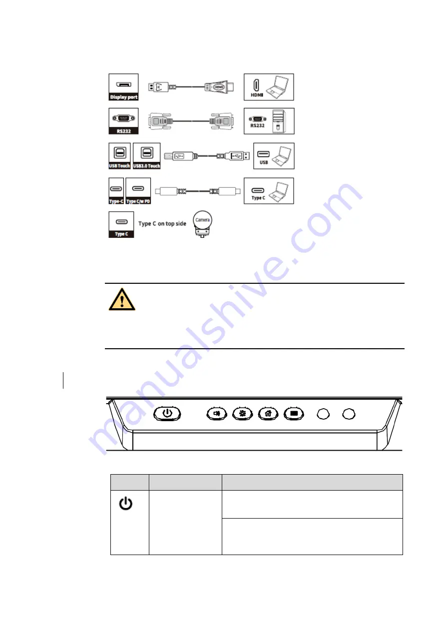
The rear power output port is supplies 5 V/2 A (maximum) power. Please contact Newline to 

purchase the power AC adapter for powering external devices. Please do not connect any 

products which require power than listed. Doing so may cause injury or damage to the panel. 

1.3 


Front Buttons 


Buttons  Operations 

Functions 


Short press 

Power on 


Solid white color : Display is on and working 

Sleep mode 


The red and white lights flicker alternately: Display 

enter Sleep mode. 

WARNING

Содержание Elara Q+ Series

Страница 1: ...1 Elara Q Series Interactive Flat Panel Display Quick Start Manual...

Страница 2: ...erence to radio communications However there is no guarantee that interference will not occur in a particular installation If this equipment does cause harmful interference to radio or television rece...

Страница 3: ...as follows Provides additional information to supplement operation in the main text Indicates a potentially hazardous situation that if not avoided could result in equipment damage data loss performa...

Страница 4: ...is not limited to an inclined plane a shaky stand desk or platform that might cause the product to turnover and be damaged Do not open the panel or change the product on your own High voltage componen...

Страница 5: ...to cause personal injury out of the reach of children Do not touch the power cable with wet hands Do not install the product in high temperature environments Do not install the product near a heat so...

Страница 6: ...s Dispose of the used battery based on your local regulations Do not damage the power cable Do not damage change twist bend or forcibly drag the power cable Do not put weights such as the product itse...

Страница 7: ...6 may be damaged CAUTION...

Страница 8: ...7 7 1 Parts and Functions 1 1 Parts Front View...

Страница 9: ...uttons 12 Power Switch 5 Remote Control Receiver 13 SDM S Slot 6 Light Sensor 14 Rear Ports 7 Proximity Sensor 15 Wi Fi Module Slot 8 Microphone 16 OPS Port Notes SDM S is Smart Display Module Small T...

Страница 10: ...ta from an external product connecting to the port please switch the signal source after the data reading is complete Otherwise the data or product may be damaged For USB use USB 2 0 provides up to 50...

Страница 11: ...external devices Please do not connect any products which require power than listed Doing so may cause injury or damage to the panel 1 3 Front Buttons Buttons Operations Functions Short press Power on...

Страница 12: ...the Quick Setting menu Long press for 5 seconds Activate Exit the power button Lock Function 1 4 Remote Control Carefully read the following instructions before using the remote control to avoid possi...

Страница 13: ...nter the Source Selection Page Return to Previous Exit App switcher Open the Quick Setting menu on the embedded operating system Open the menu in Windows system Take a Screenshot Press once to decreas...

Страница 14: ...13 2 Installation Guide 2 1 Safety Precautions Installation Environment...

Страница 15: ...urface be reinforced and have a loading capacity 4 times of the weight of the product Consult a professional installer for wall mount installation The company does not undertake relevant legal respons...

Страница 16: ...or losses incurred by users if the users fails to follow the instructions Ventilation Ensure adequate ventilation and or an air conditioned environment We recommend keeping certain distances from the...

Страница 17: ...400 mm 31 50 x 15 75 in 65INCH 600 x 400 mm 23 62 x 15 75 in Use metric M8 screws with a length of 10 mm to 15 mm 0 40 to 0 59 in to secure the touch screen to the mountingsystem Dimensions of the mou...

Страница 18: ...panel display or Wi Fi Module may be damaged The Wi Fi Module is put in accessary box with an independent package please install it onto panel referring to following steps Step 1 Unscrew the 2 screws...

Страница 19: ...ge please install it onto panel referring to following steps Use the two screws along with camera to fix Remove the silicone cover from the middle port on the top of the panel display then insert the...

Страница 20: ...e OPS protective cover Step 2 Push the OPS into the OPS port on the rear of the panel until firmly seated using the M4 screws to secure the OPS 2 7 Installing the SDM S Not Available The SDM S does no...

Страница 21: ...20 Step 2 Insert the SDM S into the port on the rear of the panel until firmly seated using the 2 screws to secure it Please install SDM S first before you hang panel on the wall...

Страница 22: ...ide of the product to I 65 75 86 Step 3 Press the power button on the front control panel or on the remote control 3 2 Power Off Press the power button on the front panel or on the remote control to e...

Страница 23: ...o red Notes Please store your session documentations before powering off the touch screen Otherwise the system will delete your session documentations after powering off Step 3 If you want to complete...

Страница 24: ...down the panel before disconnecting the power source or it may cause damage Accidental power failure may cause damage to the panel Do not repeatedly turn the power on off in a short period of time as...

Страница 25: ...enter the 6 digits passkey which is set when you first time operating the panel tap the icon to back to the previous page tap Change passkey to change your passkey tap icon to make the system enter r...

Страница 26: ...newline interactive com and choose Support Downloads Q series to download User Manual for detailed instruction manual Contact Us for Support Please email us at support newline interactive com National...

Отзывы: