7
1.5 Assembly Instructions
Step 1
. Set the burner assembly on a flat
surface. Remove the protective end cap
from the only one end of the male flared
fitting at the end of the fuel line. Leave
the other end cap on to protect the fitting
while you are doing this assembly. Screw
the male flared fitting into the inlet fitting
at the base of the burner head and tighten
using a ¾ wrench. Be sure that the
connection is tight (do not over-tighten).
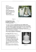
See Figure 3
(Figure 3)
Note:
The connection between the fuel line and the burner inlet fitting is brass-to
brass connection. This connection doesn’t require any thread sealing
compounds. The flare design of the threads provides a gas tight seal.
Step 2.
Carefully slide the post
(Note:
the Slip socket cover
has been assembled to the
post) over the fuel line. The post
fit one way only because the
holes drilled different positions.
The end of the post that connects
to the burner head has four
holes drilled about ½” below
the top of the post. That other
end of the post that will connect
to the support socket has four
holes drilled about 11/2” from
the other end of the post. Attach
the post to the burner assembly
using four Pan Head (Phillips) screws,
Flat washers and Lock washers. Make
sure that the setscrews firmly grip the
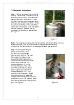
post. See Figure 4.
(Figure 4)
All manuals and user guides at all-guides.com


