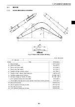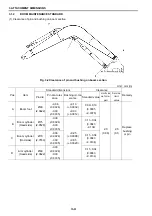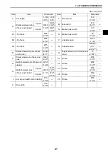
3. ATTACHMENT DIMENSIONS
3-5
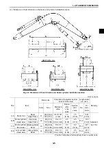
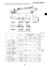
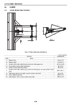
(2) Clearance in thrust direction on the boom and cylinder installation section
Fig. 3-3 Clearance in thrust direction on boom cylinder installation section
Unit : mm (in)
Pos.
Item
Basic size
Clearance X adjusted by shim
(total of both sides)
Length under
pin neck
Remedy
Code
Size
Standard
value
Repair
refer-
ence
valve
Service
limit
valve
No.
Di-
men-
sions
A-A
Boom foot
Boom
L1
360 (14.2) 0.6 (0.02)
or less
1.0
(0.04)
1.5
(0.06)
PL 1
*481
(18.9)
Adjusted
by shim
Upper frame
365 (14.4)
B-B
Boom cylinder
(Head side)
Head side
L2
95 (3.74)
0.6~1.0
(0.02~0.04)
2.0
(0.08)
2.5
(0.10)
PL 2
180
(7.09)
Upper frame
100 (3.94)
C-C
Boom cylinder
(Rod side)
Boom cylinder
L3
95 (3.74)
0.6~2.0
(0.02~0.08)
3.0
(0.12)
4.0
(0.16)
PL 3
221
(8.70)
Boom
100 (3.94)
D-D
Arm cylinder
(Head side)
Arm cylinder
L4
95 (3.74)
0.6~1.0
(0.02~0.04)
2.0
(0.08)
2.5
(0.10)
PL 4
215
(8.46)
Boom
100 (3.94)
Provide * indicates a full length as it has no under neck.
SECTION AA
PL1
SECTION CC
SECTION DD
SECTION BB
PL3
PL4
PL2
Содержание E70SR
Страница 2: ...Find manuals at https best manuals com ...
Страница 5: ...0 1 SAFETY PRECAUTIONS Find manuals at https best manuals com ...
Страница 12: ...1 OUTLINE 1 2 ...
Страница 18: ...1 OUTLINE 1 8 MEMO ...
Страница 20: ...2 SPECIFICATIONS 2 2 ...
Страница 34: ...2 SPECIFICATIONS 2 16 MEMO ...
Страница 36: ...3 ATTACHMENT DIMENSIONS 3 2 ...
Страница 51: ...This as a preview PDF file from best manuals com Download full PDF manual at best manuals com ...

