background image

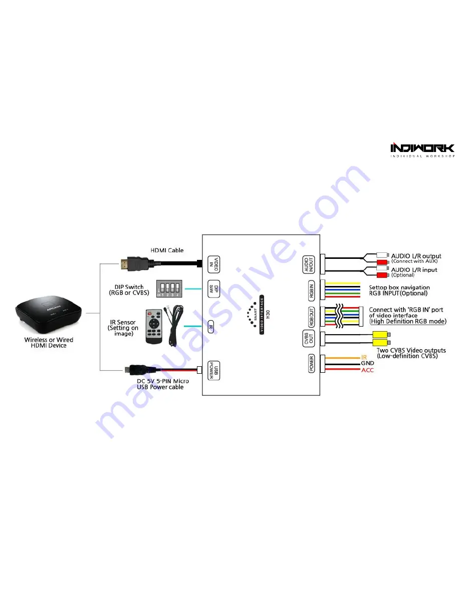
Body Connection Diagram

Содержание H30 SMART

Страница 1: ...Smartphone Mirroring System H30 SMART Mirroring Interface English Version...

Страница 2: ...igh definition RGB mode It works when combined with video interfaces for BMW Mercedes Benz AUDI etc 800 480 480 234 RGB mode selectable Low definition CVBS mode It could be used by media equipment hav...

Страница 3: ...H30 SMART Main body connectors diagram...

Страница 4: ...Wiring diagram of high definition RGB mode...

Страница 5: ...Wiring diagram of low definition CVBS mode...

Страница 6: ...OEM monitor Can not be used with dual video output RGB with CVBS at the same time One way low definition CVBS mode ex BMW 7 series F01 NET B10P video interface using external AV port Galaxy S4 Wireles...

Страница 7: ...reless mirroring type if your smartphone supports wireless mirroring devices Wired mirroring system MHL cable It supports smartphone battery charge during using mirroring GPS receiver sensitivity degr...

Страница 8: ...LG smartphones unofficially Kivic ONE KIVIC Apple iOS iPhone 4S 5 5S etc Android OS Miracast coming soon Support HDMI CVBS output Optimized for vehicle usage RTSD5000 ezguide Android OS Miracast Supp...

Страница 9: ...us LTE Tag Optimus G Optimus LTE2 Optimus Vu2 Optimus 4X Pantech Vega Racer 2 Vega LTE EX Vega LTE M Vega LTE HTC Sensation EVO 4G Flyer 4G Raider 4G Sensation XL 8X Samsung Galaxy S3 Note 2 S4 need m...

Страница 10: ...Use the dongle that fits all kinds of smartphones Wireless Multimedia Streaming for apple iOS Android OS apple TV Wi Fi AP 12V to 220V Power inverter 220V Multiple tap APCAST Dongle for android OS...

Страница 11: ...Instruction Manual H30 Smart Mirroring Interface...

Страница 12: ...e for each smartphone model OR Components Micro USB Power cable Audio Cable RGB Cable Power Cable Remote Control Manual IR Sensor CVBS Video Cable Wireless Dongle Wired Cable MICRO USB POWER IR SENSOR...

Страница 13: ...N Connector The colors of each wires can be changed under manufacturer s circumstance 1 2 X X 5 X 1 2 3 4 5 X 7 1 AUDIO R INPUT 2 AUDIO l INPUT 3 GND AUDIO INPUT 4 AUDIO R OUTPUT 5 AUDIO L OUTPUT 6 GN...

Страница 14: ...Body Connection Diagram...

Страница 15: ...de 480 234 800 480 OEM monitor Navigation Set top box optional Audio In optional Audio Out RGB In optional RGB Cable Splice the IR wire with DT or IR wire Installation Diagram of RGB Mode LVDS IN OUT...

Страница 16: ...SB Power Cable DIP S W CVBS mode PAL NTSC Audio Out optional CVBS input port Video Audio CVBS Video Out Audio Out Monitor or device supported CVBS input Installation Diagram of CVBS Mode Rear Monitor...

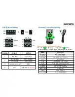
Страница 17: ...4 times and press No 1 button It shows numbers on the left top of screen when you press the 3 button MEMU FUNCTION Brightness Adjust the brightness Contrast Adjust the contrast Saturation Adjust the...

Страница 18: ...Distributed by Manufactured by...

Страница 19: ...Copyright indiwork All Rights Reserved...

Отзывы: