


[ENG] UniPing server solution v4/SMS & UniPing server solution v3, User guide -[USS] Sockets and Indication Elements
[USS] Sockets and Indication Elements
–
Voltage of the logic "0": <0,9V
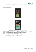
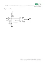
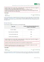
It is possible to plug relay coils to UniPing Server Solution v3/SMS IO lines directly. A voltage of triggering a relay
should be either 12 V or 5 V, and a triggering current - no more than 200mA. Control relay contacts are connected to
an IO terminal and to the te12 V or 12 V relay or a +5 V terminal for a 5 V relay. A corresponding IO line
should be set to an output mode. When connecting several relays, there is a need to take into consideration that
their summed maximum triggering current should not exceed 200mA.
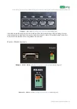
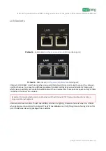
IO STATE LEDs
IO STATE LEDs
(see picture 1 and picture 2)
signal about a status of the first four IO lines. When a LED is turned on, a
corresponding IO line is in a status logic 1, and a turned off LED means a logic status 0.
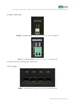
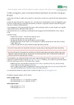
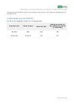
Thermo / IR Terminals
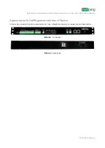
Picture 3
– Terminals «Thermo / IR»
(
UniPing server solution v4/SMS
)
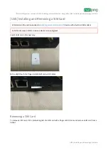
Picture 4
– Terminals
«Thermo / IR»
(
monitoring unit)
A THERMO/IR terminal block is used to plug temperature sensors and an IR-transceiver. To make plugging sensors
convenient, connecting terminals are output to a front panel twice. Temperature sensors can be plugged into a left
terminal block as well as into a right one. An IR transceiver is plugged in
parallel
to temperature sensors into the
same terminals.