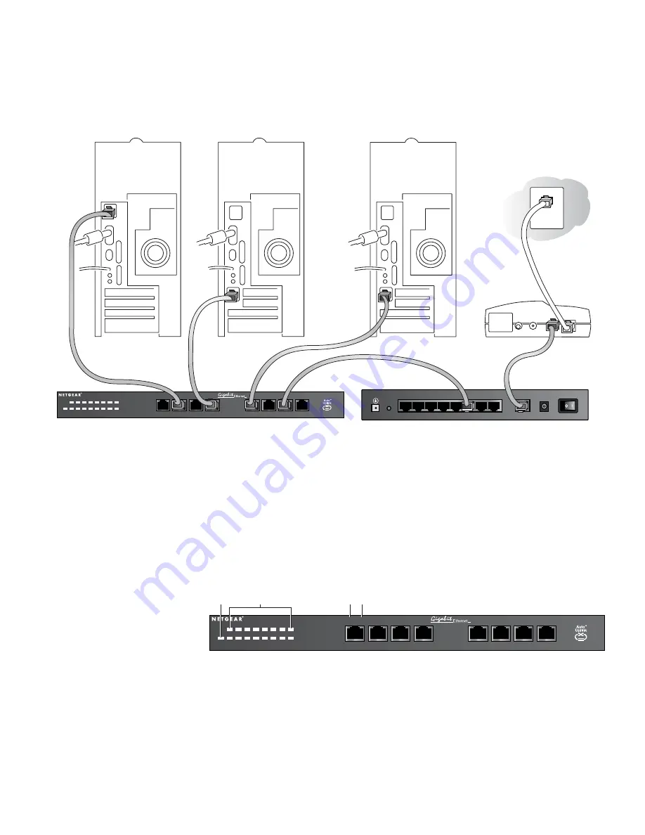
Install the Switch and Connect the
Other Devices
1.
Place the switch on a flat surface or hook onto the screws.
2.
For each device, insert one end of an Ethernet cable into the port in the device and insert
the other end into one of the Ethernet ports on the switch.
3.
Connect the power adapter’s cord into the back of the switch and then plug the adapter
into a power source (such as a wall socket or power strip).
The Power light
should light up.
The corresponding
Link LED for each
connected and
powered device
should light and flash when activity occurs. If the connection is 1,000 Mbps or 100
Mbps, the LED in the RJ-45 jack will light up. If the connection is 10 Mbps, the 10M
LED on the left side of the front panel will light up.
Note:
If any light doesn’t operate as indicated, go to the
Troubleshooting
section.
3
3
Pwr
10M: On=Link, Blink=Act
On=Link, Blink=Act
1000M 100M
Green=FDX, Yellow=Collision
1 2 3 4 5 6 7 8
1
2
3
4
5
6
7
8
10/100/1000 Mbps Gigabit Switch
GS108
12VDC 1.2A
8
7
6
5
4
3
2
1
LOCAL
10/100M
INTERNET
OFF
ON
DSL
modem
Apple G4
PC with
GA302T
Adapter
Server with GA622T
Adapter
GS108 8-Port 10/100/1000 Mbps
Gigabit Ethernet Switch
FVS318 Cable/DSL ProSafe VPN Firewall
Pwr
10M: On=Link, Blink=Act
On=Link, Blink=Act
1000M 100M
Green=FDX, Yellow=Collision
1 2 3 4 5 6 7 8
1
2
3
4
5
6
7
8
10/100/1000 Mbps Gigabit Switch
GS108
Model GS108 8-Port 10/100/1000 Mbps Gigabit Ethernet Switch
Power
1000M
LED
100M
LED
Link, Act, FDX,
Collision LED


