background image

Installation Guide for the Model FE508 and FE516 Fast Ethernet Hubs

2-4

Physical Description

Normal/Uplink Push Button

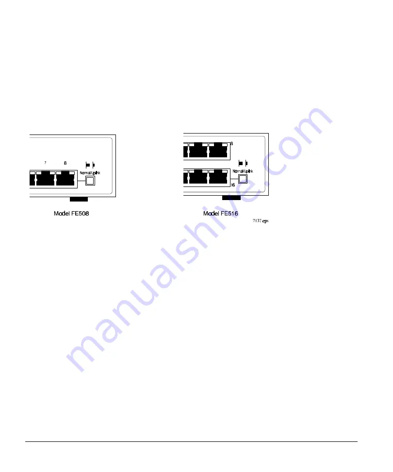
The Normal/Uplink push button (see Figure 2-3) on the front panel of the hub allows you to select
Uplink (MDI-X) or Normal (MDI) wiring for Port 8 on the Model FE508 hub and Port 16 on the
Model FE516 hub. Ports 8 and 16 are configured for Normal wiring when the push button is in the out
position. When the push button is pressed in, Ports 8 and 16 are configured for Uplink wiring.

Figure 2-3.  Normal/Uplink push button

The Normal/Uplink push button eliminates the need to use a cross-over cable if you are connecting
the same type of devices. Use the following guidelines to configure Ports 8 and 16 for Uplink or
Normal wiring:

• 

Configure Ports 8 and 16 for Normal wiring if the remote end of the cable is connected to an
Uplink-wired device (such as a network station or a router).

• 

Configure Ports 8 and 16 for Uplink wiring if the remote end of the cable is connected to a
Normal device, such as a 10/100 Mbps switch.

The remaining (Normal) ports on the hubs cannot be configured for Uplink wiring. If you are using
one of these ports to connect to another Normal port, you must use an RJ-45 cross-over cable to
connect the two ports (refer to Appendix C, “Fast Ethernet and Cabling Guidelines,” for information
on the cross-over and straight-through cables).

Содержание FE508 - Hub

Страница 1: ...Installation Guide for the Model FE508 and Model FE516 Fast Ethernet Hubs NETGEAR Inc A Bay Networks Company 48105 Warm Springs Blvd Fremont CA 94539 USA June 1996 Document Number M FE500NA 0...

Страница 2: ...Hubs are shielded against the generation of radio interference in accordance with the application of Council Directive 89 336 EEC Article 4a Conformity is declared by the application of EN 55 022 1987...

Страница 3: ...rference may be caused to equipment such as radios and TV receivers Customer Support For assistance with installing and configuring your NETGEAR systems or with post installation questions or problems...

Страница 4: ...100BASE T Hub 3 2 Installing the Hub on a Flat Surface 3 3 Installing the Hub in a Rack 3 4 Installing Multiple Hubs 3 6 Stacking and Cascading Hubs 3 6 Installing and Connecting Multiple Hubs 3 6 Ve...

Страница 5: ...Assignments RJ 45 Connector B 1 Appendix C Fast Ethernet and Cabling Guidelines Fast Ethernet C 1 Fast Ethernet Cabling C 1 Cable Guidelines C 2 Cable Lengths C 2 Cable Specifications C 3 Twisted pai...

Страница 6: ...cations on powerful workstations require more bandwidth than the conventional 10BASE T network By migrating users who require more bandwidth to devices that operate at 100 Mbps you can increase the ba...

Страница 7: ...s the potential for configuration errors Stackable chassis equipped with 8 or 16 fast 100BASE TX ports to provide fast information exchange resource sharing and client or peer to peer communication us...

Страница 8: ...hub is divided into the front panel components and the rear panel components Use the key at the bottom of each illustration to determine the associated component Front Panel The front panel contains...

Страница 9: ...el FE516 Fast Ethernet hub LED Display There are three LEDs on the front panel of the hub and two on each port connector that allow you to identify Status of the hub AC power supply Operational status...

Страница 10: ...panel of the Model FE508 hub provides 8 RJ 45 100BASE TX ports and the Model FE516 provides 16 RJ 45 100BASE TX ports These standard RJ 45 connectors accept 2 pair or 4 pair Category 5 unshielded twis...

Страница 11: ...ed to use a cross over cable if you are connecting the same type of devices Use the following guidelines to configure Ports 8 and 16 for Uplink or Normal wiring Configure Ports 8 and 16 for Normal wir...

Страница 12: ...The rear panel of the hub provides two cascade cable connectors a Terminator LED two cooling fans and an AC power receptacle see Figure 2 4 1 Cascade Up and Cascade Down connectors 2 Terminator LED 3...

Страница 13: ...consist of any combination of Model FE508 and Model FE516 hubs daisy chained together using a NETGEAR supplied cascade cable The cascade cable daisy chains between the Cascade Down and Cascade Up con...

Страница 14: ...in those hubs The Terminator LED on the center hubs should not be lit Use Table 2 2 to determine which hubs in a stack should have the terminator active LED on Table 2 2 Terminator LED status in a st...

Страница 15: ...as direct sunlight warm air exhausts or heaters Humidity Between 5 and 85 noncondensing Ventilation Minimum 2 inches 5 08 cm on all sides for cooling Adequate airflow in room or wiring closet Operati...

Страница 16: ...nstallation Guide for the Model FE508 and FE516 Fast Ethernet Hubs 3 2 Installation Wiring hardware Wiring hardware such as punchdown blocks or patch panels should be complete before installing the hu...

Страница 17: ...our dealer if there are any wrong missing or damaged parts Keep the carton including the original packing materials Use them to repack the hub if there is a need to return it for repair To qualify for...

Страница 18: ...s completed the Underwriters Laboratories UL or Electronic Testing Laboratories ETL certification process Termination method To minimize crosstalk noise maintain the twist ratio of the cable up to the...

Страница 19: ...power cord s first to the power entry receptacle on the hub rear panel and then to the wall 6 Continue with the steps in Verifying Your Installation later in this chapter Installing the Hub in a Rack...

Страница 20: ...tegory 5 UTP wiring and connectors to the RJ 45 connectors Refer to Appendix C Fast Ethernet and Cabling Guidelines for wiring rules and guidelines 5 When installation for each hub in your stack is co...

Страница 21: ...r panel of the hub and the supplied cascade cable provide the ability to stack and link up to four hubs This stack then functions as a single repeater or collision domain By stacking hubs you can expa...

Страница 22: ...k or on the shelf or tabletop Refer to Installing the Hub in a Rack or Installing the Hub on a Flat Surface earlier in this chapter 2 Disconnect the power cords from the hubs you are connecting CAUTIO...

Страница 23: ...nnector on the top hub is empty The Cascade Down connector on the bottom hub is empty The Terminator LED is lit on the top and bottom hub The Terminator LED is not lit on the middle hubs Figure 3 4 Fo...

Страница 24: ...ED on each connected port should be on Data LED on the front panel is blinking when data is being received by any port in the hub and the Data LED on the connected port is blinking when data is being...

Страница 25: ...Description for a description and location of the LEDs Verifying the LED Conditions At power on verify the following LED conditions Power LED is on Link LED on each connected port is lit Terminator L...

Страница 26: ...is powered on and that there is a proper connection at that end If the Link LED is intermittent check the port termination at both the hub and device ends Check the crimp on the RJ 45 connectors In a...

Страница 27: ...collisions can result when multiple hubs are cascaded and when many computers are connected on the network Incorrect cabling connectors and wiring techniques are other causes for excessive collisions...

Страница 28: ...h use the same Carrier Sense Multiple Access with Collision Detection CSMA CD Media Access Control MAC protocol Both 100BASE T and 10BASE T Ethernet use the same type of Ethernet frame and error detec...

Страница 29: ...onnected to a printer or in a segmented network with multiple users or workgroups and other networking devices The following examples are shown in this chapter 100BASE TX shared repeater Building smal...

Страница 30: ...ffect network performance is congestion In many LAN environments the primary problem is access to the server When many users are connected and accessing one server on a 10 Mbps link congestion and col...

Страница 31: ...Configuration Examples Figure 5 2 illustrates 100 Mbps users connected to a Model FE516 hub accessing a common server integrated with the NETGEAR Model SW502 Ethernet Switch and a Model EN516 Etherne...

Страница 32: ...twork the Model SW507 Ethernet Switch with six 10 Mbps ports and one 100 Mbps port can be used to segment each of the hub s 10 Mbps traffic By adding the switch overall bandwidth and throughput are in...

Страница 33: ...3u 100BASE TX Fast Ethernet IEEE 802 3 CSMA CD Data Rate 100 Mbps with 4B5B encoding and MLT 3 physical interface for 100BASE TX Interface RJ 45 connector for 100BASE T Ethernet interface Electrical S...

Страница 34: ...ltitude 10 000 ft 3 000 m maximum Storage altitude 10 000 ft 3 000 m maximum Electromagnetic Emissions Meets requirements of CE mark commercial FCC Part 15 Class A EN 55 022 CISPR 22 Class A VCCI Clas...

Страница 35: ...strates the RJ 45 connector used for port connections on hubs Table B 1 provides the pin out information for the Normal MDI X RJ 45 connector and the pin out information for the Uplink MDI port Port 8...

Страница 36: ...an switch and route data from 10 Mbps to 100 Mbps without protocol translation and its associated delays Fast Ethernet is based on the proven CSMA CD Media Access Control MAC protocol The most popular...

Страница 37: ...Certification Make sure that your Category 5 UTP cable has completed the Underwriters Laboratories UL or Electronic Testing Laboratories ETL certification process Termination method To minimize crosst...

Страница 38: ...ctrical requirements of the Category 5 cable Table C 1 Electrical requirements of Category 5 cables Specification Category 5 Number of pairs Two or Four Impedance 100 15 Mutual capacitance at 1 KHz 5...

Страница 39: ...s and switch ports are media dependent interfaces with cross over ports referred to as MDI X or Normal ports Computers and workstation adapter cards are usually media dependent interface ports referre...

Страница 40: ...connector commonly called RJ 45 is used to connect stations hubs and switches to unshielded twisted pair UTP cable The RJ 45 connector accepts 4 pair Category 5 UTP In a Fast Ethernet network it is im...

Страница 41: ...ng NEXT loss and achieving more reliable system performance is to select the cable pairs within the cable that have the highest twist rate highest NEXT loss Selecting a cabling system that uses compon...

Страница 42: ...bling C 2 Category 5 UTP cable 3 3 C 1 Category 5 UTP wiring 2 3 chassis 2 1 configuration examples 5 2 migration to 100 Mbps 5 3 multiport switch 5 5 shared repeater 5 2 connectors cascade 2 6 Cascad...

Страница 43: ...owner registration card 3 2 P package contents 3 2 pads self adhesive 3 3 pairing 3 3 panel front 2 1 rear 2 5 3 7 pin assignments RJ 45 connector B 1 port connection troubleshooting 4 2 ports RJ 45...

Страница 44: ...net Hubs Index 3 T temperature requirements 3 1 termination 3 3 2 Terminator LED 2 7 tools required for installation 3 2 topology star wired C 1 troubleshooting table 4 2 U Uplink wiring 2 4 user requ...

Отзывы: