220-0000071 rev01
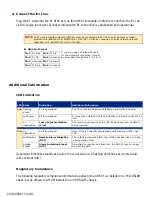
4. Connect the E1 Line.
Plug the E1 cable into the E1 RJ45 port on the UIM-E1 faceplate. Verify the connection; the E1 Lnk
LED will pulse (once per second) to indicate the E1 connection is established and operational.
Additional Information
LED Indicators
(A pulsing LED blinks steadily at a rate of once per second. A flashing LED blinks at a more rapid,
less constant rate.)
Regulatory Compliance
The following regulatory compliance information applies to the UIM-E1 as installed in a Mini DSLAM
chassis or as affixed to a MUM installed in an IP DSLAM chassis.
NOTE
An E1 Uplink Interface Module (UIM-E1) must be connected via E1 line to an E1 network extender
provider unit (ENE2000-P or ENE2000-P-12-AC/DC). A UIM-E1 connected to an E1 network extender
subscriber unit (ENE2000-S) will not function.
E1 RJ45 Port Pinout
Pin 1
Rx Ring
Pin 5
Tx Tip
Pin 2
Rx Tip
Pin 6
not used
Pin 3
not used
Pin 7
not used
Pin 4
Tx Ring
Pin 8
not used
If you are using a shielded E1 cable
for your Network connection, it must
be grounded through Pins 3, 6, 7 & 8.
LED State
Indication
Additional Information
Lnk
flashing
green
E1 is operational
The E1 connection has been established and traffic is flowing.
solid green
E1 is operational
A connection exists but there is indication of a problem with the E1
line.
no
illumination
Loss of Synchronization
(LOS)
The incoming connection to the UIM-E1 has been lost; no data is
being received.
Alm
no
illumination
E1 is operational
Note: If the E1 Lnk LED also remains unlit then the UIM-E1 has
LOS.
solid amber
Remote Alarm Indication
(RAI)
The outgoing connection from the UIM-E1 has been lost; no data
is being transmitted.
pulsing
amber
Alarm Indication Signal
(AIS)
An indirect connection has been lost; the UIM-E1 may no longer
be receiving data.


