220-0000022 rev03
Clock Source and Transmit Line Buildout
Switch Configuration
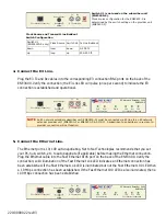
4. Connect the E3 Line.
Plug the E3 Tx and Rx cables into the corresponding E3 connection BNC ports on the back of the
ENE3400. Verify the connection; the E3 Lnk LED will pulse (once per second) to indicate the E3
connection is established and operational.
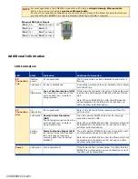
5. Connect the Ethernet Line.
The Ethernet port is 10/100 auto-negotiating. Net to Net Technologies recommends that you set
your PC, hub, switch, etc. to auto-negotiate (if applicable) before making the Ethernet connection.
Plug the Ethernet cable into the Fast Ethernet RJ45 port on the back of the ENE3400. Verify the
connection; solid illumination of the Fast Ethernet Lnk LED indicates an Ethernet connection has
been established. If the Fast Ethernet Lnk LED is illuminated but not the Fast Ethernet 100 LED then
a 10 Mbps connection has been established. If the Fast Ethernet 100 LED is also illuminated, then a
100 Mbps connection has been established.
Tx
Rx
Power Adapter
Config
Fast Ethernet Connection
5V DC
E3 Connection
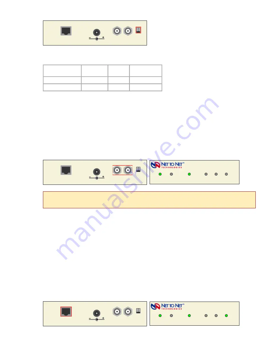
Switch #1 is not used on the subscriber unit
(ENE3400-S).
Clock source configuration for the ENE3400-S is
determined by the switch setting on the provider unit
(ENE3400-P).
Switch #1
(ENE34000-P only)
Clock Source Switch #2 Tx Line Buildout
down
local
down
0-255 ft.
up
loop
up
255-450 ft.
Tx
Rx
Power Adapter
Config
Fast Ethernet Connection
5V DC
E3 Connection
E3 Network Extender 3400
ENE3400-S
Lnk
Alm
Power
100
Act
Lnk
E3 Connection
Fast Ethernet Connection
NOTE
An E3 network extender subscriber unit (ENE3400-S) must be connected via E3 line to an E3 network
extender provider unit (ENE3400-P or ENE3400-P-6-AC/DC). A subscriber-to-subscriber or provider-to-
provider connection will not function.
Tx
Rx
Power Adapter
Config
Fast Ethernet Connection
5V DC
E3 Connection
E3 Network Extender 3400
ENE3400-S
Lnk
Alm
Power
100
Act
Lnk
E3 Connection
Fast Ethernet Connection


