


10
11
NC-1000 -
installation manual
10
11
5.1.2 Bringing cable to the frame
Either the top entry or the bottom entry can be used. Cables are brought to the frame outside
of the back side where they are earthed if necessary and from where the fibres are brought to
the inner frame and to the splice trays in their protection tubes.
It is worth of noting that the cables are not fixed permanently to the frame until they have been
spliced.
Cables are brought to the frame as follows:
Release the locking of the inner frame from its bottom and turn it out as much as it goes.
•
Draw the cable ends through the frame below its lowes fixing plate.
•
Draw the cable ends enough out from the frame over their stripping lenght. The stripping
•
length is about 250 cm.
Measure about 250 cm stripping lengths of the cables starting from the sheath removal
•
points and cut away the extra lenghts.
5.1.3 Preparation and earthing of cables
Remove the cable sheaths starting from the sheath removal marks.
•
Prepare and earth the cables according to the instructions of the cable supplier.
•
Two examples are described in the chapters 4.1.3.1 and 4.1.3.2. It should be noted that
•
these are only examples. In every case the instructions of the cable supplier shall be
carefully followed.
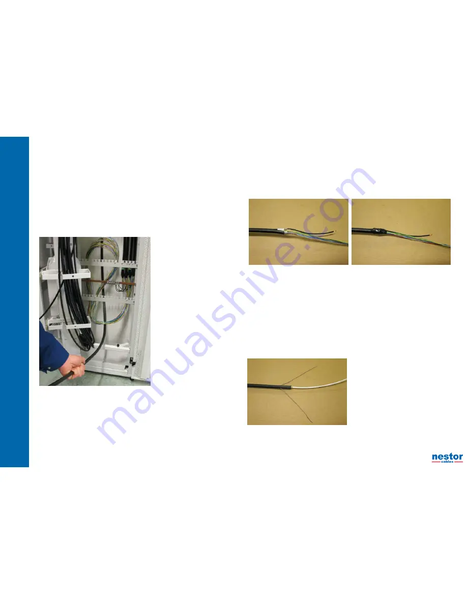
5.1.3.1 Stranded loose tube cables
Cut the cable sheath from the sheath removal point marked before.
•
Remove the cable sheath about 10 cm from the cable end and find the rip cords.
•
Split the cable sheath with rip cords to the sheath removal point and about 30 mm over it.
•
Cut the parts of the cable sheath from the sheath removal point.
•
Remove all protective layers over the fibre tubes.
•
Separate the fibre tubes and the possible fillers from each other.
•
Cut the central element and the possible fillers at the point where the sheath has been cut. Note, if the
•
cable has metallic central element cut it to the length of about 20 cm.
Straighten the fibre tubes by using a hot air blower or hot water. If you use a hot air blower, be careful
•
that the fibre tubes dont’t get too hot.
Connect the connector of the earthing conductor to the possible aluminium laminate or corrugated steel
•
tape. Protect the connection point with an insulating tape.
5.1.3.2 Central loose tube cable
Expose the strength elements on both sides of the cable and turn them up to the sheath removal point
•
marked before. Cut them to the length of about 20 cm and bend them on both sides.
In the case of a cable with aluminium laminate or corrugated steel tape remove the sheath and other
•
protective layers up o the distance of 50 mm from the sheath removal point. Remove the cable sheath
in several parts.
In the case of non-metallic cable remove the sheath and protective layers up to the sheath removal
•
point. Remove the sheath in several parts.
Remove the sheath from the possible aluminium laminate or corrugated steel tape with a hot air blower
•
and pliers.
Use e.g. a steel brush or a knife to remove also the possible plastic coating from the laminate or steel
•
tape in order to ensure the electrical contact for earthing.
In the case of metallic strength elemens turn them to the same side of the cable and then at the
•
distance of about 30 mm from the cable towards the cable end. Try to get them as straigth as possible
and also near each other that they can be easily guided to the earthing connector. Cut them to the
same length as the aluminium laminate or corrugated steel tape.
Cut the central tube at the distance of 30 mm from the aluminium laminate or steel tape and in a case of
•
non-metallic cable at the distance of 30 mm from the cable sheath. Cut the central tube by making first
a scratch around the tube and then bending the tube carefully at the both sides until it breaks.
Take a hold from the fibres with fingers and pull the central tube away.
•