


In
st
al
lati
on
s
te
p b
y s
te
p
9
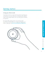
2. Connect to power and the control circuit
Check the heating system’s wiring to determine what
type it is.
Remove the Heat Link cover and connect the L (live)
and N (neutral) terminals on the Heat Link to the L and
N circuit on the boiler or junction box. This will power
the Heat Link.
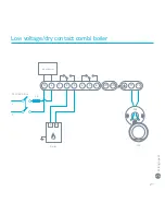
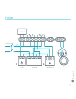
Connect the heating control circuit to the Heat Link 1
(normally closed/satisfied), 2 (common), 3 (normally
open/call-for-heat) as needed.
If the system has a hot water control circuit, connect it
to 4 (normally closed/satisfied), 5 (common), 6 (normally
open/call-for-heat) as needed.
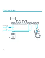
If you have an OpenTherm boiler, connect its control
circuit to the OT1 and OT2 terminals.
→ See pages 20-25 for detailed wiring diagrams.
INS
TAL
LING
THE HEA
T LINK
Содержание A0001
Страница 1: ...Installation step by step Learning Thermostat Installation Guide ...
Страница 5: ...Installation step by step 5 Display Base Heat Link Screws Trim plate In the box ...
Страница 20: ...230 V combi boiler L N Boiler 12 V 3 A 230 V AC 50 Hz N L 1 2 3 4 5 6 OT1 OT2 T1 T2 L N Input power 20 ...
Страница 24: ...OpenTherm boiler L N OT boiler N L 1 2 3 4 5 6 OT1 OT2 T1 T2 OT1 OT2 Input power 12 V 3 A 230 V AC 50 Hz 24 ...
Страница 30: ......
Страница 31: ......
Страница 32: ...064 00197 GB A ...