Notice:
Please read the following instructions before istallation.
A. Please handle the lock carefully. Any damage of the structure or the armature plate will reduce the
magnetic force.
B. Fix the lock on the door frame and the armature plate on the door leaf. The accessories can provide
better conjuction to the lock and the armature plate.
C. Please keep the door closed when you drill holes.
D. Fasten the screws of the lock.
E. The limit value of the reed switch of the door signal detection is 0.5A/30VDC. Don't overload.
F. Make sure the armature plate can be slighly shaken when locked, for the rubber washers need some
space to adjust the position of the armature plate and the lock.
G. Please select the correct wiring for 12VDC or 24VDC voltage input.
!
Installation instruction
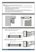
Wiring diagram
www.nerival.fi
Nerival Oy
24VDC:
Red wire is Positive pole ”+”, Black wire as Negative Pole ”-”
and connect Orange and Blue wires together.
12VDC:
Connect Red and Orange wire as Positive pole ”+”
Connect Blue and Black wire as Negative Pole ”-”
24VDC
POWER
+
-
12VDC
POWER
+
-
COM
Red
Orange
Blue
Black
White
Green
Red
Orange
Blue
Black
White
Green
NC
COM
NC


