background image


SKG4-E Gas Fired Humidifier 

Installation Instructions and User Manual 


www.neptronic.com


Page | - 48 - 


Idle Screen 

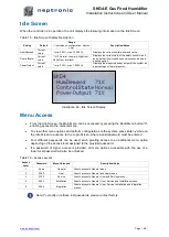
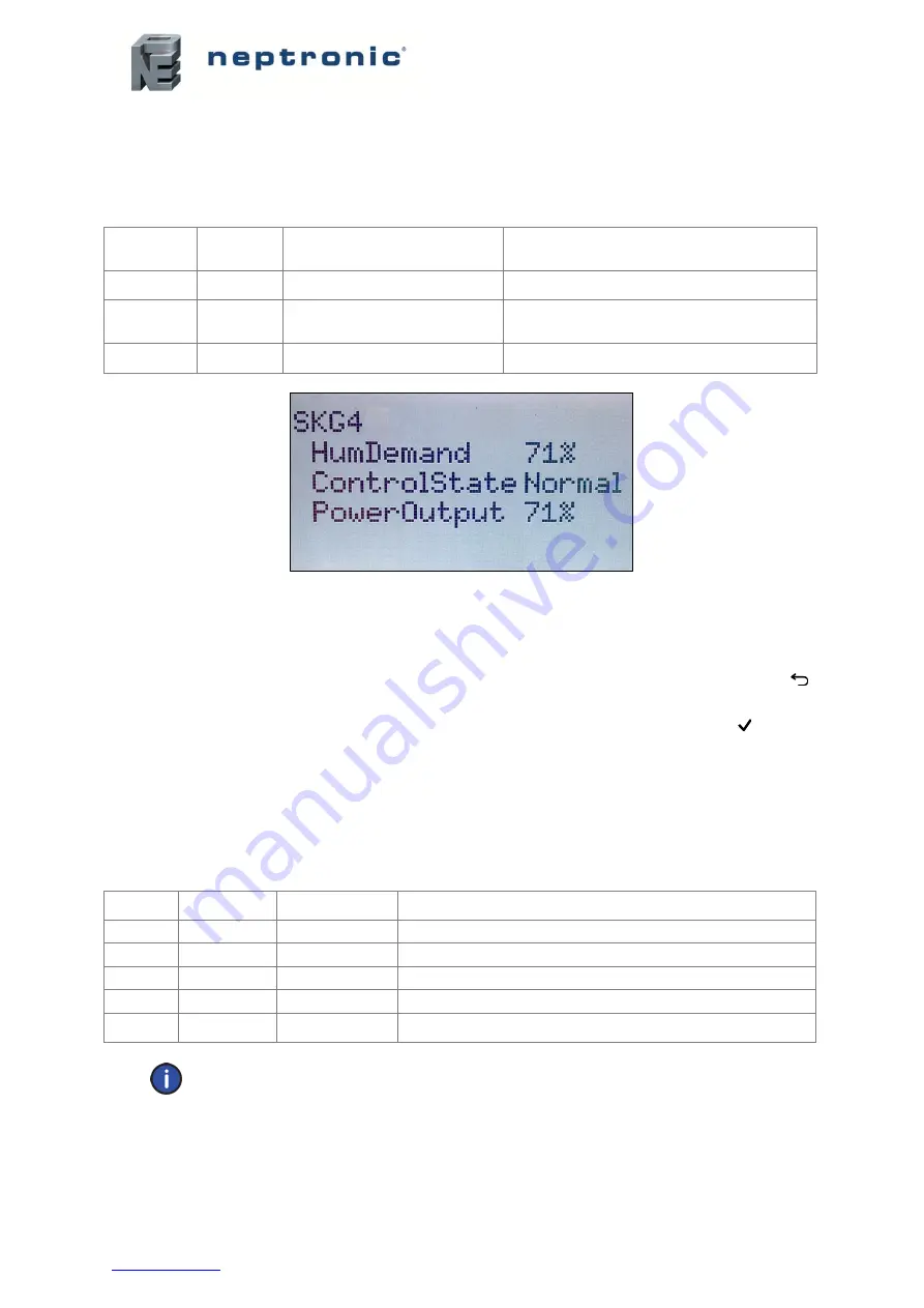
When the controller is in operation, the unit displays the following information on the Idle Screen: 

Table 15 - Idle Screen Display Description 

Setting


Default


Range 

(

* indicates no configuration; display 

only)


Description/Notes 

HumDemand: 

Current 
value 

* (min: 0.00%, max: 100.00%) 

Displays the current humidity demand value. 

ControlState: 

Current 
value


* (Off, Normal, LowLimit, HighLimit, 
NoAirFlow, Interlock) 

Displays the current state of the safety control circuit 
and whether the circuit has been disconnected due to 
a safety switch. 

PowerOutput: 

Current 
value 

* (min: 0.00%, max: 100.00%) 

Displays the measured power output of the system as 
a percentage of the total power. 


Illustration 48 - Idle Screen Display 

Menu Access 


From the Idle Screen, the Main Menu can be accessed by pressing the Back/Menu button 

enabling access to the General menu.  


To view other menu options and perform configurations to the system, press Enter   while on 
the Idle Screen to advance to the Login Screen, where a valid password must be entered.  


Four  different  passwords  can  be  used,  each  granting  access  to  an  additional  menu  option 
depending on the access level assigned to the provided password.  


If  a  password  of  higher  access  is  provided,  all  menu  options  accessible  with  the  use  of  a 
lower level password will also be unlocked.  

Table 16 - Access Levels 

Access 

Level 

Password 

Menu Unlocked 

Description/Notes 

None 

General 

Grants access to General menu. 

2222 

User 

Grants access to General and User menus. 

3322 

Service 

Grants access to General, User and Service menus. 

4433 

Installation 

Grants access to General, User, Service and Installation menus. 

5544 

Integration 

Grants access to General, User, Service, Installation and Integration 
menus. 


Note: To modify or retrieve lost passwords, please contact factory. 


Содержание SKG4-E Series

Страница 1: ...SKG4 E ESA 181203 Gas Fired Humidifier SKG4 E Series Installation Instructions and User Manual READ AND SAVE THESE INSTRUCTIONS ...

Страница 2: ...cal installation MUST only be performed by skilled and qualified technical personnel such as an electrician or a technician with appropriate training The customer is always responsible for ensuring the suitability of the technical personnel Ensure that the local regulations concerning the provision of electrical installations are followed Health and Safety Neptronic has considered the aspects of t...

Страница 3: ... your responsibilities as outlined in the Health and Safety regulations The control of Legionella bacteria in water systems and your SKG4 humidifier must be included in the risk assessment of the water system in your building as a whole In particular if the humidifier is turned off for prolonged periods you must ensure that the unit is drained and that stagnation is avoided in pipe work supplying ...

Страница 4: ...anual These installation and operation instructions have been developed to facilitate the installation of the SKG4 humidifier The strict application of these instructions will ensure the conformity of your installation and operation as per the manufacturer s recommendations The application of these instructions is one of the conditions for the application of the warranty The application of these i...

Страница 5: ...earances Weather Proof Enclosure 17 Weather Proof Enclosure Installation on Floor Roof 18 Weather Proof Enclosure Installation on Roof Curb 18 Stage 2 Steam Distribution Installation 19 Fundamental Design Concepts 19 Weather Proof Enclosure Steam Outlets 20 Steam Outlet Dimension and Quantity Weather Proof Enclosure 20 Steam Dispersion General Recommendations 21 Selection of Steam Distribution Man...

Страница 6: ... 41 Electrical Control Connections 41 Safety Contact Connections 41 Dry Contacts 41 Humidifier Control 42 Analog Signals 42 Humidity Control by Humidistat External Mode 42 Humidity Control by Humidifier Internal Mode 43 Humidity Control by External Source 44 Network Communication 45 Controls Placement Steam Dispersed into a Duct or AHU 46 Controller Configuration 47 Control Panel Features 47 Idle ...

Страница 7: ... and Approved Code of Practice L113 The regulation imposes duties on employers self employed persons and persons who have control to any extent of lifting equipment The SKG4 humidifier MUST be handled and lifted with care at all times and remain in its original packaging for as long as possible prior to installation The SKG4 humidifier package may be carried using a forklift from the underside Exe...

Страница 8: ...of Modules Steam Capacity kg hr Input Capacity kW Current at 230V A No of Outlets Multi Steam Header Diameter mm SKG4 E0501 N P 1 50 49 3 5 1 76 SKG4 E0701 N P 1 70 63 3 5 1 76 SKG4 E0801 N P 1 80 70 3 5 1 76 SKG4 E1001 N P 1 100 73 3 5 1 76 SKG4 E1202 N P 2 120 112 4 5 2 100 SKG4 E1502 N P 2 150 126 4 5 2 100 SKG4 E1702 N P 2 170 136 4 5 2 100 SKG4 E2002 N P 2 200 146 4 5 2 100 SKG4 E2503 N P 3 2...

Страница 9: ...r and heat exchanger Electrical power connection Steam outlet Flue vent connection either side Gas supply inlet either side Water supply either side 316SS Evaporation chamber shown in DOWN position Front door Drain outlet either side Quick connect water outlet Back door Water level sensor Controller Illustration 2 Humidifier Overview ...

Страница 10: ...ons mm Weight kg Qty Dia mm A B C D E F G H I Empty Full of Water SKG4 E0501 N P SKG4 E0701 N P SKG4 E0801 N P SKG4 E1001 N P 1 1 Ø76 1372 610 560 280 470 145 200 SKG4 E1202 N P SKG4 E1502 N P SKG4 E1702 N P SKG4 E2002 N P 2 2 Ø76 1372 1220 560 280 470 610 1080 274 384 SKG4 E2503 N P SKG4 E2703 N P SKG4 E3003 N P 3 3 Ø76 1372 1830 560 280 470 610 1080 1690 431 600 SKG4 E3504 N P SKG4 E3704 N P SKG...

Страница 11: ... Dimensions mm Drain Outlet Diameter Pan Drain Diameter Water Inlet Diameter Gas Inlet Diameter Flue Outlet Diameter SKG4 E0501 N P SKG4 E0701 N P SKG4 E0801 N P SKG4 E1001 N P 1 Ø20 Ø15 Ø15 Ø25 Ø76 SKG4 E1202 N P SKG4 E1502 N P SKG4 E1702 N P SKG4 E2002 N P 2 Ø40 Ø15 Ø15 Ø25 Ø100 SKG4 E2503 N P SKG4 E2703 N P SKG4 E3003 N P 3 Ø40 Ø15 Ø15 Ø40 Ø125 SKG4 E3504 N P SKG4 E3704 N P SKG4 E4004 N P 4 Ø40...

Страница 12: ...mensions and Weight Ducted Combustion Model No of Modules No of Air Inlet s Air Inlet Dia mm Dimensions mm J K L M N O SKG4 E0501 N P SKG4 E0701 N P SKG4 E0801 N P SKG4 E1001 N P 1 1 Ø51 448 352 SKG4 E1202 N P SKG4 E1502 N P SKG4 E1702 N P SKG4 E2002 N P 2 2 Ø51 448 352 609 962 SKG4 E2503 N P SKG4 E2703 N P SKG4 3E003 N P 3 3 Ø51 448 352 609 962 1571 SKG4 E3504 N P SKG4 E3704 N P SKG4 E4004 N P 4 ...

Страница 13: ... SUPPLY WATER SUPPLY DRAIN Connections 1 to 3 Module Configuration Connections 4 Module Configuration Illustration 6 Weather Proof Enclosure Table 5 Dimensions and Weight Weather Proof Enclosure Model No of Modules Dimensions mm Weight kg T U V W Empty Full of Water SKG4 E0501 N P SKG4 E0701 N P SKG4 E0801 N P SKG4 E1001 N P 1 1898 778 845 736 285 340 SKG4 E1202 N P SKG4 E1502 N P SKG4 E1702 N P S...

Страница 14: ...Model Number and Quantity SKG100 SKG150 SKG180 SKG200 SKG4 E0501 N P 1 x1 SKG4 E0701 N P 1 x1 SKG4 E0801 N P 1 x1 SKG4 E1001 N P 1 x1 SKG4 E1202 N P 2 x1 x1 SKG4 E1502 N P 2 x2 SKG4 E1702 N P 2 x1 x1 SKG4 E2002 N P 2 x2 SKG4 E2503 N P 3 x1 x1 x1 SKG4 E2703 N P 3 x1 x2 SKG4 E3003 N P 3 x3 SKG4 E3504 N P 4 x1 x1 x2 SKG4 E3704 N P 4 x1 x3 SKG4 E4004 N P 4 x4 Module 4 Module 1 Master Module 2 Module 3...

Страница 15: ... technicians with appropriate training The customer is responsible for ensuring their suitability For the installation of the SKG4 humidifier and its associated components no special tooling is required above that of a fitter s toolkit Installation Steps Stage 1 Unit Positioning and Mounting Stage 2 Steam Distribution Installation Stage 3 Gas Supply Connection Stage 4 Water Supply Installation Sta...

Страница 16: ... with the outside air Humidifier flue gases must be vented to the outdoors Locate the humidifier as near as possible to an outside wall or roof so that the flue pipe from the humidifier is short and direct Locate the SKG4 humidifier on a water proof floor or install a drain pan beneath the humidifier The humidifier must be installed in a way that ensures the steam hose length is kept to the shorte...

Страница 17: ...ll be affected by altitudes over 1050m above sea level Please refer to the table below to anticipate the ratio of output reduction Table 7 Output Reduction Based on Altitude Altitude Above Sea Level m Output Reduction 0 to 1050 0 1051 to 1350 2 1351 to 1650 4 1651 to 1950 6 1951 to 2250 8 Minimum Clearances The following minimum clearances are indicated for inspection and servicing access The SKG4...

Страница 18: ...spection and servicing access The SKG4 humidifier is designed for a zero clearance to combustible materials Leave a clearance of at least 0 8 m to the front panel and 0 6 m on the left and right sides of the humidifier Leave a clearance of at least 0 5 m on top of the humidifier 24 0 6m minimum 30 0 8m minimum 20 0 5m minimum 24 0 6m minimum Illustration 10 Weather Proof Enclosure Clearances ...

Страница 19: ...not supplied to secure the humidifier to the floor roof Illustration 11 Floor Roof Installation Weather Proof Enclosure Installation on Roof Curb W U 1 2xU 1 2xW Ø 12mm to bolt humidifer to roof curb Illustration 12 Roof Curb Installation Ensure that the roof curb is structurally built to support the weight of the SKG4 humidifier The roof curb must provide proper level to the humidifier The base o...

Страница 20: ... lowest point s of the steam supply piping The steam separator S trap must be installed higher than the static pressure of the system by at least 51 mm Use rigid copper piping whenever possible Flexible steam hoses can be used for short runs up to 5 m or for interconnecting between rigid pipe runs Ensure that there are no kinks and that the hose does not sag when using flexible tubing Do not use f...

Страница 21: ... an outlet located on either one of the sides of the humidifier By default the steam outlet will be on the right side of the humidifier when facing the control panel The steam outlet location can be switched to left side upon request to factory Steam Outlet Dimension and Quantity Weather Proof Enclosure Table 8 Steam Outlet Dimensions and Quantity Weather Proof Enclosure Model Steam Outlet Quantit...

Страница 22: ...Manifolds The minimum steam manifold length that can be used with the models SKG4 E0501 to SKG4 E1001 is 900mm Any manifold below this dimension will have insufficient outlet spigots to allow proper steam distribution If the duct has a width below 900mm it will be necessary to either fit multiple pipes or use a Multi Steam system S A M E2 System Positioning the S A M E2 The steam manifold must be ...

Страница 23: ...ntal Duct Note Steam pipe must be supported on the end by appropriate duct hanger or strap supplied by others Placement of Steam Pipe in Vertical Duct 2 Pipes 3 Pipes Illustration 18 Pipe Placement Vertical Duct H 24 minimum 600mm 1 5 H 2 5 H 8 200mm air H 36 minimum 900mm 1 6 H 1 2 H 1 3 H 10 250mm 10 250mm air W 24 minimum 600mm 1 2 W 1 4 W 1 4 W W 36 minimum 900mm 1 3 W 1 3 W 1 6 W 1 6 W ...

Страница 24: ...pipe must be connected to two S A M E2 steam manifolds with a suitable reduction at the lowest point to allow a Ø15mm condensate drain from the main steam supply Single Module Humidifiers SKG4 E0701 to SKG4 E1001 Min 7 pipe slope Ø3 76mm Ø 15mm Steam distribution manifolds S A M E2 minimum length 35 900mm Min 4 100mm Insulated pipe H Air Duct Static pressure 2 50mm Min 1 3 H Total length of steam ...

Страница 25: ...t they can be placed side by side For installation of Multi Steam units refer to the Neptronic Multi Steam Installation Instructions Ø 15mm Static pressure 2 51mm Min 2 51 mm Min 2 51mm Min 2 51mm Mounting bracket must be level horizontally Steam supply hose or rigid pipe to Humidifier Header must be pitched toward condensate drain Condensate drain pipe to steam trap Air duct Rod bolt nut and wash...

Страница 26: ...must be connected to a single Multi Steam with a suitable reduction at the lowest point to allow a Ø15mm condensate drain from the main steam supply 2 Module Humidifiers SKG4 E1202 to SKG4 E2002 min 7 pipe slope Ø3 76mm Ø3 76mm Ø4 100mm Ø 15mm Min 7 pipe slope Static pressure 2 50mm Insulated pipe Air Duct Total length of steam conduit must not exceed 16ft 5m Illustration 24 Multi Steam Steam Pipe...

Страница 27: ...t the lowest point to allow a Ø15mm condensate drain from the main steam supply 4 Module Humidifiers SKG4 E3504 to SKG4 E4004 min 7 pipe slope Ø 15mm Static pressure 2 50mm Ø 20mm Min 7 pipe slope Insulated pipe Air Duct Ø3 76mm x2 Ø4 100mm x2 Total length of steam conduit must not exceed 16ft 5m Illustration 26 Multi Steam Steam Pipe Work SKG4 E3504 to 4004 Two Ø76mm steam outlets attached to a s...

Страница 28: ...rate pressure regulator for each humidifier connected to the gas line Ensure that the humidifier is not connected to the same regulator as any other gas appliances Pipes must be inspected for dirt and chips after threading and reaming the end of pipes Gas piping installation must be supported to avoid mechanical strain stress Two wrenches must be used when connecting gas piping to the humidifier D...

Страница 29: ... capacity gas flow and length of main SKG4 GAS LINE NPT DN6 Plugged Taping for Test Pressure Gauge Turn Gas Valve Drip Pocket Illustration 27 Gas Supply Connection Gas Leak Test Pressure testing of the gas supply piping must be performed by the gas installer in accordance with local codes and regulations Test pressure must be relieved from the gas piping system prior to opening the manual shut off...

Страница 30: ... safe operation the use of softened water is not recommended If a third party requires a water softener for any operational or equivalency purposes ensure that the water dilution feature is enabled To enable this function configure the value of the BlowdownRate setting located in the Installation menu see page 55 for details Water Inlet Specifications o Maximum water supply pressure 70 to 480kPa o...

Страница 31: ...e Gasket Gasket Illustration 28 Water Supply Connections Double Check Valve In order to comply with WRAS Water Regulations Advisory Scheme regulations in force in the United Kingdom a double check valve must be installed as indicated in the above illustration All connections must be made using the gaskets provided On the inlet side of the check valve shown is a compression fitting for a 15mm pipe ...

Страница 32: ...on Size Open Drain Minimum Size SKG4 E0501 to 1001 Ø22mm Ø15mm Ø80mm SKG4 E1202 to 2002 Ø36mm SKG4 E2503 to 4004 Ø50mm Ø100mm Water Drain Installation Water drain outlet connection must be connected to drain pipe of sufficient size It is recommended to use standard copper hydraulic pipes of sufficient size Minimum water drain pipe gradient must be of 6 5mm per 300mm horizontal run No drain trap is...

Страница 33: ...r W U 1 2xU 1 2xW Pan drain outlet Ø 0 6 15mm Illustration 31 Weather Proof Enclosure Base Pan Drain Outlet Dimension Weather Proof Enclosure Water Drain Valve The weather proof enclosure is equipped with a normally open valve enabling the humidifier to drain all water during a power failure in order to prevent water from freezing within the unit During normal operation the humidifier reduces drai...

Страница 34: ...ke vent s must be equipped with a weather cap and bird screen in order to prevent gusts of wind or water from entering preventing mold build up or leakage in the ducts The SKG4 humidifier has filtered air openings through the front door Do not block or obstruct the humidifier air openings The humidifier is factory adjusted for correct performance Do not alter throttle setting or restrict blower co...

Страница 35: ...ply Installation of the combustion air duct must be as direct as possible minimizing the number of turns or elbows with a maximum of 6 elbows in total Use only duct materials suitable to supply air from the outside to the humidifier Combustion air duct length and flue gas venting pipe must not exceed o 30m 3m x total number of 90 elbow 1 5m x total number of 45 elbow Combustion air duct must be in...

Страница 36: ...01 to SKG4 E1001 Combustion air Flue gases Humidifier inlet Ø2 51mm Ø2 51mm minimum Illustration 33 Ducted Combustion Air 1 Module 2 Module Humidifiers SKG4 E1202 to SKG4 E2002 Flue gases Com bustion air Humidifier inlet Ø2 51mm 1 to 2 Outlet manifold Ø4 100mm minimum Ø2 51mm minimum Illustration 34 Ducted Combustion Air 2 Modules ...

Страница 37: ...ses Com bustion air 1 to 3 Outlet manifold Ø6 100mm minimum Humidifier inlet Ø2 51mm Ø2 51mm minimum Illustration 35 Ducted Combustion Air 3 Modules 4 Module Humidifiers SKG4 E3504 to SKG4 E4004 Flue gases Com bustion air 1 to 4 Outlet manifold Ø8 205mm minimum Humidifier inlet Ø2 51mm Ø2 51mm minimum Illustration 36 Ducted Combustion Air 4 Modules ...

Страница 38: ...te chimney as a flue gas venting system The flue gas venting system must not extend into or pass through any circulation air duct or plenum Installation of the flue gas venting pipes must be as direct as possible minimizing the number of turns or elbows with a maximum of 6 elbows in total If flue gas venting pipe length exceeds 6 1m the exhaust vent pipe must be insulated in order to reduce the fo...

Страница 39: ...1 Minimum Spacing When Flue Gas Terminal is Located Towards Outside Air Minimum Spacing mm Building or Other Element 300 Below adjacent opening window air vent or any other ventilation opening 75 Below a gutter drain or soil pipe 200 Below eaves catch or balcony 75 Beside vertical drain or soil pipe 300 Beside adjacent corner or other flue gas terminal 150 Beside adjacent opening door window air v...

Страница 40: ...Page 39 Steam Outside wall Drip trap Flue gas venting pipe minimum 2 upward grandient Vent terminal to prevent backflow due to outside weather conditions Humidifier single flue gases outlet Important this connection must be air tight Illustration 37 Typical Flue Gas Installation 3 Modules ...

Страница 41: ...d disconnect circuit breaker must be installed on the supply adjacent to the humidifier To provide strain relief to the supply cable install a knock out not supplied at the bottom of the electrical compartment of the humidifier Ensure that the size of the wire conductors is appropriate for the maximum current supplied Ensure that the incoming power cable is secured via suitably sized cable gland E...

Страница 42: ...ust be wired between terminals TB3 1 2 If this contact opens operation of the SKG4 unit will stop The unit will display the airflow switch as open but will not generate an alarm If an airflow switch is not used install a jumper between terminals TB3 1 2 The High limit humidistat contact must be wired between terminals TB3 1 3 If this contact opens operation of the SKG4 unit will stop and an alarm ...

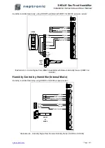
Страница 43: ...g humidifiers the analog signal s must be connected between terminals TB4 1 and TB4 3 4 and or 5 To configure the source of the signal s access the Control sub menu located in the Installation menu see page 55 Humidity Control by Humidistat External Mode Humidity controlled externally using HRO20 humidistat TB4 TB3 TB2 TB5 TB6 Airflow switch High limit humidistat Interlock Control Demand Room Humi...

Страница 44: ...MOD RH HRO20 humidistat SHR10 or SHC80 RH Input 1 2 3 COM 24 VAC RH 1 2 12 13 14 15 16 1 2 Illustration 42 Control Signal from HRO20 Humidistat with Remote Humidity Sensor SHR10 or SHC80 Humidity Control by Humidifier Internal Mode Humidity controlled internally using SHR10 or SHC80 as space sensor TB4 TB3 TB2 TB5 TB6 Airflow switch High limit humidistat Interlock Room Humidity Common 24 Vac 24 Va...

Страница 45: ...ifier Installation Instructions and User Manual www neptronic com Page 44 Humidity Control by External Source Humidity controlled externally using an external signal source Illustration 44 Control Signal from External Device ...

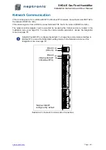
Страница 46: ...ted by accessing the Control sub menu located in the Installation menu see page 55 To setup the communication parameters access the Integration menu see page 57 Note BACnet MS TP is configured by default To change the communication interface to Modbus RTU access the NtwrkOption setting located in the Network sub menu of the Integration menu see page 57 TB4 TB3 TB2 TB5 TB6 A B RS 485 BACnet MS TP o...

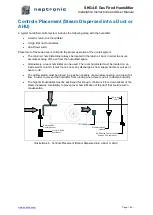
Страница 47: ... The room humidistat must be located on an inside wall or column It must not be near any discharge air from supply ducts or sources of heat or cold The airflow switch must be placed in a position capable of accurately opening on a loss of air flow in order to prevent the humidifier from running when there is no air to absorb humidity The high limit humidistat must be positioned far enough minimum ...

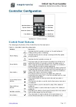
Страница 48: ...n Even when the humidifier is powered off the controller remains operational Drain Button The drain button is used to manually activate the drain cycle Must be pressed and held for 3 seconds to perform the related action in order to prevent accidental activation Even when the humidifier is powered off a drain cycle may be initiated Once the manual drain cycle is completed the system will automatic...

Страница 49: ...in Menu can be accessed by pressing the Back Menu button enabling access to the General menu To view other menu options and perform configurations to the system press Enter while on the Idle Screen to advance to the Login Screen where a valid password must be entered Four different passwords can be used each granting access to an additional menu option depending on the access level assigned to the...

Страница 50: ...nu category and press Enter to advance to the next sub menu B Use the and buttons to increase and decrease values Use the buttons to scroll to the next or previous parameter Values are saved as soon as a change is made C Press the Back Menu button to go back one menu The current menu location is displayed at the top of the screen D To exit completely press the Back Menu button until you return to ...

Страница 51: ...Current value min 0 00 max 100 00 Displays the measured humidity demand of the humidifier module ServiceDue Off Off On Displays whether the humidifier module is due for servicing ModuleState Current value Off Idle LineRinse TankRinse Filling Draining Heating Boiling Alarm PurgeAir Displays the current state of operation of the humidifier module Control RoomDemand Current value min 0 00 max 100 00 ...

Страница 52: ...alue min 0 00 C max 125 00 C Units C F Displays the temperature of water in the evaporation chamber WtrFreq Current value 0 Hz 30000 Hz Displays the measured input frequency of the water level sensor AmbientTemp1 to 4 Current value min 40 00 C max 100 00 C Units C F Displays the temperature value inside of the weather proof enclosure Only appears for units with the weather proof enclosure FanFdbac...

Страница 53: ...n software version SerialNo Displays the serial number of the humidifier Profile Displays a short profile for the configured device MCULoad Current value min 0 0 max 100 0 Displays the current microcontroller load MemoryLoad Current value min 0 0 max 100 0 Displays the current memory load Runtime Current value min 0 sec max 999999999 sec Displays the number of seconds that the system has been powe...

Страница 54: ...Loop 1 Only appears if ModHLProfile is set to an internal control mode or HumCntrlHLSrc is set to SupplyHLDemand SupplyHLStp 80 00 min 0 00 max 100 00 Define the supply high limit demand setpoint value System LocalDateTime YYYY MM DD 00 00 00 Configure the current date and time Interface Local Display 5 BacklightLvl 25 min 0 max 100 Select the backlight level of the LCD screen Contrast 5 min 0 max...

Страница 55: ...perform an air purge Mod1Request None None Reset Alarms Drain Reset Counters Filling WaterCalib PurgeAir Perform one of the following actions for the first humidifier module reset service counters initiate a drain cycle reset warning alarms fill the evaporation chamber calibrate the water level sensor or perform an air purge Mod2Request None None Reset Alarms Drain Reset Counters Filling WaterCali...

Страница 56: ...ode profile for the modulating high limit demand Select the Custom option to configure individual settings Network option only applicable for BACnet models RoomDemandLoop 2 Only appears if ControlProfile is set to an internal control mode or HumCntrlDemandSrc is set to RoomDemand RoomRHSrc None None RoomRH Network Select the reading source for the room demand Network option only applicable for BAC...

Страница 57: ... The drain cycle setting does not affect the AFEC system IdleTempStpnt 0 C min 0 C max 60 C Units C F Set the idle temperature setpoint value for the evaporation chamber when there is no demand IdleTime 24hr min 0hr max 72hr Set the amount of time the humidifier can remain in standby mode until an automatic drain cycle is performed ServInterval 1000hr min 100hr max 1000hr Set the time of operation...

Страница 58: ...et server BACnetMSTP 10 For models connected to BACnet MSTP MaxMaster 127 min 1 max 127 Configure MaxMaster value to increase network efficiency when there are less than 127 devices on the network For optimal efficiency set value to the highest MAC address in the MS TP network MaxInfoFrames 1 min 1 max 100 Configure the maximum number of information messages the controller may transmit before it m...

Страница 59: ...ation port number Modbus TCP port number is set by default KeepAliveTimeOut 120min min 0min max 1440min Set the amount of time the communication stays open before connection is cut out when no signal is received from the device Communication IPSettings 10 DHCP Inactive Inactive Active Select whether to enable Dynamic Host Configuration Protocol DHCP to automatically provide an IP address RstIPSett...

Страница 60: ...uring draining due to a blockage in the pipes Verify and remove any obstructions in the piping and ensure that the drain outlet is not clogged Manual HeatTimeout Indicates that the water temperature in the evaporation chamber has not reached the boiling point within the programmed delay Verify the temperature of the supply water Manual Overheat Indicates that the evaporation chamber temperature se...

Страница 61: ...d Gas Supply 9 Confirm that a proper regulator and gas test point have been installed on the gas line to the humidifier 10 Confirm that gas is supplied to the humidifier and that the shut off valve located outside the humidifier is closed With the shut off valve is turned on check for leaks gas smell or hissing sounds Flue Gas Venting 11 Verify that the flue gas venting is as follows a Ensure that...

Страница 62: ...From a cold water start the humidifier will require 5 to 10 minutes to produce steam The humidifier controller will indicate the water temperature and flue gas temperature g During normal operation while steam is produced the water temperature must be 100 C and the flue gas temperature must be around 120 to 200 C The water level percentage must not indicate less than 95 h Once the evaporation cham...

Страница 63: ...ble in order to ensure proper functionality Cleaning the Humidifier Cleaning the humidifier involves the following steps Stage 1 Drain the Evaporation Chamber Stage 2 Shut Down the Electrical Supply Stage 3 Remove the Evaporation Chamber Stage 4 Clean the Evaporation Chamber Stage 5 Clean the Other Components Stage 6 Reinstall the Evaporation Chamber Stage 7 Restart the Humidifier Stage 1 Drain th...

Страница 64: ...e 4 Clean the Evaporation Chamber 1 Remove the residue that has accumulated inside the chamber and poor out any remaining water that is on the bottom of the container 2 To clean out the remaining scale from the container use a stiff brush synthetic filament only and some vinegar or any weak acid suitable for cleaning stainless steel WARNING The use of a wire brush or any non recommended acid will ...

Страница 65: ...unters and clear the alarm warning after servicing a Using the control panel access the Request setting located in the Command sub menu of the Service menu b Select the Reset Counters value and press Enter to reset the service counters 6 Ensure that the drain cycles are set for every 6 hours of operation This is the factory default setting and is recommended for city water To configure the drain c...

Страница 66: ...es of O2 CO2 CO NO and NOX These values must lie within the values listed in the SKG4 Combustion Field Adjustment Instructions If any value is above the acceptable limit the combustion needs to be readjusted The readjustment must be done by skilled and qualified technical personnel Refer to the SKG4 Combustion Field Adjustment Instructions for more details on the combustion adjustment procedure Fl...

Страница 67: ...o the igniter Use caution while removing the igniter as it is very fragile It is recommended to have a spare igniter on hand 7 Disconnect the vent from the top of the evaporation chamber 8 Remove the combustion chamber flange air gas supply tube and burner as follows a Remove the nuts that attach the top of the evaporation chamber from the housing b Lower and remove the top of the chamber from the...

Страница 68: ...drain Drain valve is clogged Check the drain valve During a drain or foaming cycle the water level sensor has sensed that the water level has not decreased Verify that the drain pump the fill and drain water pipe connections and the water level sensor chamber are not obstructed Humidifier is always on Foam cycle FoamSensor setting displays Foam Excessive foaming condition inside the evaporation ch...

Страница 69: ...ons have been made An ignition lock out 1 flash fault signal occurred due to High temperature switch Inspect the electrical wires connecting the gas control module and gas valve and ensure proper connection Replace the igniter Defective igniter A weak flame 2 flash fault signal has been detected due to Incorrect positioning of the igniter Have the igniter position verified and adjusted by skilled ...

Страница 70: ...Notes ...

Страница 71: ......

Страница 72: ...au blvd Montreal Qc H4N 1R6 Canada www neptronic com Toll free in North America 1 800 361 2308 Tel 514 333 1433 Fax 514 333 3163 Customer service fax 514 333 1091 Monday to Friday 8 00am to 5 00pm Eastern time ...

Отзывы: