


6
7
Connecting PVG-C controller to a BDG-256 gateway (Option)
A BDG-256 gateway can connect one or multiple PVG-C controllers, and upload the monitoring
data from PVG to NEPVIEWER monitoring website. For details of BDG-256 gateway and
NEPVIEWER, please refer to the user manual of BDG-256 gateway.
Connecting BDG-256 gateway to PVG-C is optional, and shall not affect the rapid shutdown
function of PVG-C and PVG-4.
WARNING:
ONE PVG-C CAN ONLY MONITOR ONE CHANNEL OF PV PANELS (ONE MPPT).
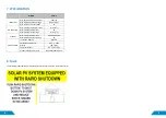
5. OPERATING INSTRUCTIONS
WARNING:
PVG RAPID SHUTDOWN SYSTEM SHALL BE CHECKED REGULARLY TO MAKE SURE IT
FUNCTIONS PROPERLY. TEST SHALL BE DONE AT DAYTIME, AND BY MANULLAY PUSH DOWN THE
EMERGENCY BUTTON. SOLID GREEN LIGHT SHALL BE ON WITHIN 10 SECONDS AFTER THE EMERGENCY
BUTTON IS PUSHED.
WARNING:
IN ORDER TO MAKE THE RAPID SHUTDOWN FUNCTION PROPERLY, THE VOLTAGE ON THE DC
BUS CAPACITOR OF THE STRING INVERTER SHALL BE REDUCED TO LESS THAN 30Vdc WITHIN 10 SECONDS,
USING ONE OF THE FOLLOWING APPROACHES:
1)
A DC SWITCH ON THE DC INPUT OF THE STRING INVERTER IS SWITCHED OFF WITHIN 10 SECONDS TO
DISCONNECT THE DC BUS OF THE INVERTER
2)
IF THE INVERTER DC BUS CANNOT BE DISCONNECTED, A “BLEEDING” RESISTOR SHALL BE
CONNECTED ACROSS THE DC INPUTS OF THE STRING INVERTER AND DISSIPATE THE ENERGY ON THE
DC BUS WITHIN 10 SECONDS
PVG is powered by the PV panel. Thus the rapid shutdown is operable during daytime when
the PV panel is energized. Rapid shutdown can be activated by one of the following two
operations:
Option-1 Press the E-STOP button on the PVG controller (PVG-C)
Option-2 Disconnect AC adapter to the PVG-C remote controller
Flashing LED on the PVG-1/2/3/4 indicates the status of the switch inside the PVG.
LED on PVG-4
-
Status
OFF for 5 seconds, ON for 1 second
PVG switch is connected
OFF for 1 second, ON for 1 second
PVG switch is disconnected
OFF for 2 second, ON for 1 second
PVG status error
There are two LEDs on the PVG-C. RED LED flashing indicates the
controller is powered, while the green LED on PVG-C indicates the DC voltage is safe.
Green LED on PVG-C
Status
OFF
PV array DC voltage is above 30Vdc
ON
PV array DC voltage is below 30Vdc
To re-connect the PV panels, a re-connection command can be send to each PVG by
the following steps:
Step-1: Plug AC adapter into the PVG-C
Step-2: Release the E-Stop button on PVG-C
This operation can only be done at day time since the PVG is powered by PV panels. In
most cases, all panels are re-connected immediately following the steps above.
6. PV PANEL MONITORING USING BDG-256
Using BDG-256 gateway, DC current, voltage, power, daily energy, and
temperature of each PV panel can be monitored using MICROVIEWER
locally, or NEPVIEWER remotely. BDG-256 usage should refer to the
BDG-256 gateway manual. Connection of BDG-256 and PVG-C is as
follows:
Содержание PVG-4
Страница 4: ...4 5 PVG 4 System Diagram ...


