N58 Hardware User Guide
Chapter 5 Application Interfaces
Copyright © Neoway Technology Co., Ltd. All rights reserved.
55
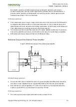
The analog audio traces must be surrounded with ground and comply with differential trace
rules. Isolate the traces from digital signals and clocks as well as other analog signal cables.
Avoid crossing audio cables with other cables. Reserve enough ground holes and ground
protection.
5.5 Video Interfaces
5.5.1 LCD
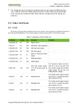
N58 has an SPI interface dedicated to the LCD function, and supports the highest frame rate of
LCD display QVGA@30 fps. The following table provides the description of LCD function pins.
Table 5-1 Description of LCD function pins
Pin Name
Pin No.
I/O
Function
Remarks
LCD_RST_N
63
DO
Reset control
-
LCD_TE
64
DO
Data frame read ready flag -
LCD_SPI_CS
65
DO
SPI chip select signal
-
LCD_SPI_CLK
66
DO
SPI clock signal
-
LCD_SPI_SDC
67
B
Data or command control
signal
-
LCD_SPI_SIO
68
B
Data input/output
-
LCD_SPI_SEL
73
DO
Select signal
-
VDD_LCD
138
PO
LCD main power supply:
1.8 V DC power supply by
default
The maximum output current is
200 mA. It can be used for LCD
main power supply and interface
power supply. Do not use it as
backlight power supply.
LED_K0
139
PI
Backlight LED
The anode power supply range is
3.45 V to 4.3 V, and the maximum
input current is 50 mA.
LED_K1
140
PI
Backlight LED
The anode power supply range is
3.45 V to 4.3 V, and the maximum
input current is 50 mA.
LED_K2
141
PI
Backlight LED
The anode power supply range is
3.45 V to 4.3 V, and the maximum
input current is 50 mA.


