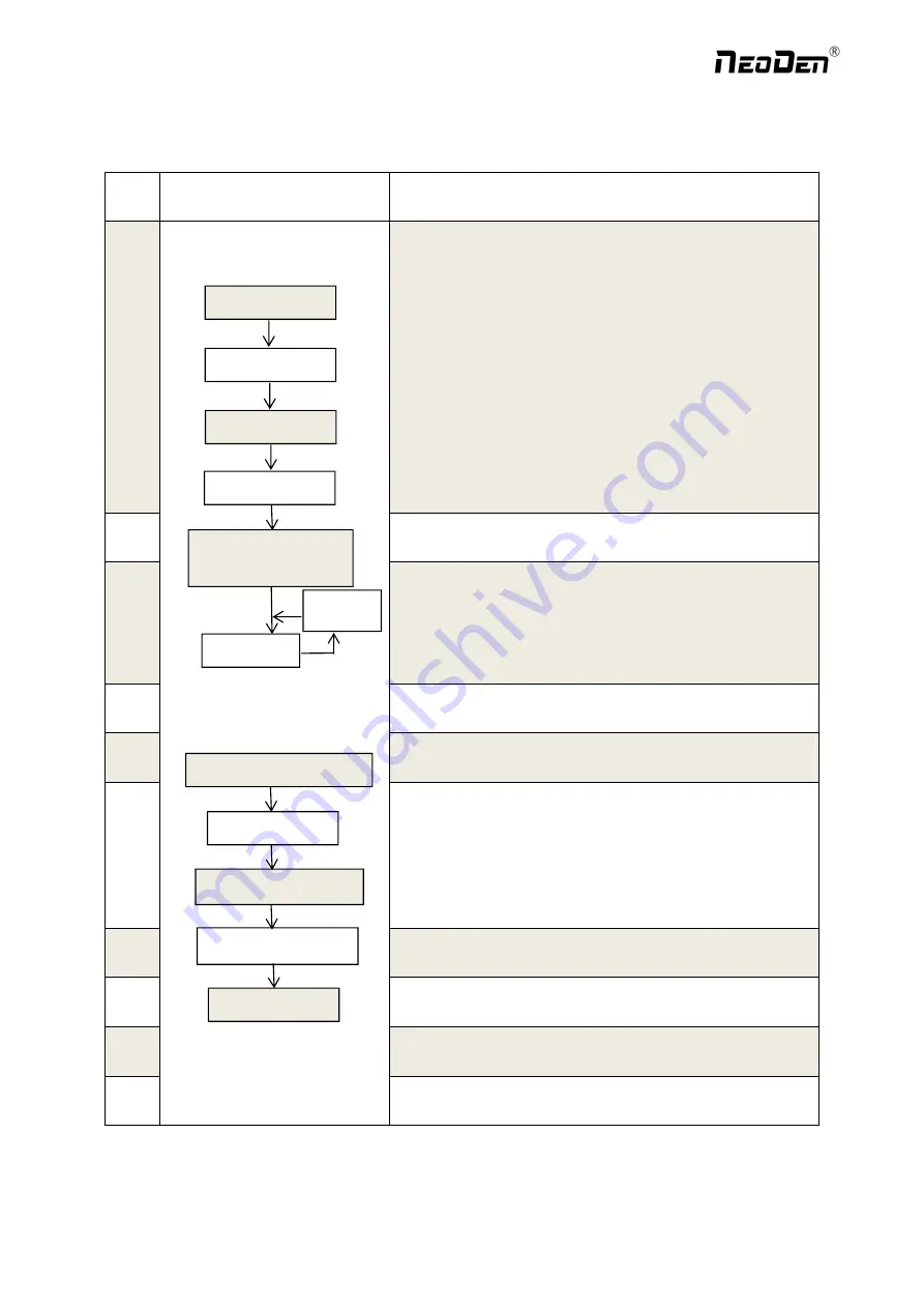
1.5 Operation flow chart
NO.
Flow chart
Note
1
1. The pick and place machine is a precision equipment. In the
installation position of the machine, it is necessary to carry out horizontal
correction before and after the equipment to prevent the uneven operation
of the equipment from damaging the service life of the equipment;
2. Connect and fix the equipment interface before and after the
equipment, and connect and fix the ground wire;
3. The access power must meet the requirements of power identification;
4. No less than 0.6mp air source input and adjust the pressure value to
OK;
5. Check the safety of the working area of the mounting head;
6. The XY transmission parts are not fastened and interfered, and check
that the emergency stop switch is in normal state;
2
Power on and turn the power switch clockwise;
3
1
,
1. When the self-test is carried out, the head indicator light of the
mounting head and the light source of the IC camera will be on and
flash briefly to indicate that the self-test is normal;
2
,
XY initialization (origin reset) is normal, the software enters the file
list interface, and no error report pops up;
4
After power on, directly enter the file list page;
5
See page 10 for the introduction of machine operation for
details;
6
Suggestions on production process:
1. First component confirmation: confirm the component angle
and polarity, component picking position and mounting
position;
2. Start production after confirming solder paste printing and
temperature setting;
7
Production process;
8
After the production is finished, reset the origin and prepare to
shut down;
9
Shut down the system via computer, then power off the
machine.
10
Disconnect the electricity supply after the system being
powered off.
Software shut down
System shut down
Power OFF
Exit
Production Finished
Preparation
Power ON
Automatic Test
Power on page
Program and Edit;
Production
Shutdown steps
Mounting
Modify
Abnormal
Start-up steps
9
Zhejiang
NeoDen Technology Co.,Ltd.
Содержание K1830
Страница 6: ...1 3Working Area Structure Figure 3 Top view of main mounting area 6 Zhejiang NeoDen Technology Co Ltd ...
Страница 7: ...Figure 4 X axis Beam Figure 5 Main Placement Head Camera 7 Zhejiang NeoDen Technology Co Ltd ...
Страница 35: ...8 2 Component Positions Setup 35 Zhejiang NeoDen Technology Co Ltd ...
Страница 44: ...11 Structure and maintenance instruction 11 1 Feeder Brief Introduction 44 Zhejiang NeoDen Technology Co Ltd ...


