CHAPTER 2. MPO-700
2.2. OPERATING ELEMENTS
Warning:
Always check for and secure all places where the robot might drop down before bringing it into
operation.
2.1.4 Qualified Personnel
This product must only be modified, commissioned, operated and serviced by qualified personnel.
The requirements on qualified personnel can be found at
(page 39).
2.1.5 Safety Instructions
Please also check the general safety instructions for Neobotix robots which can be found at
(page 32).
2.1.5.1 Danger Areas
Omni Drive Modules
The four Omni Drive Modules integrated into the MPO-700 are touch proof while not moving and protected against
dust and splash-water. It is nevertheless possible that objects or body parts (e.g. hands or feet) get damaged or injured
when touching the drive modules during operation. Objects or limbs may get squeezed or crushed if they get pulled in
by a drive wheel or when the robot drives over them.
Great care is required while working on or with the robot to avoid such injuries or damages. Depending on the
application it can be necessary to design and mount protective covers around the drive modules.
2.2 Operating Elements
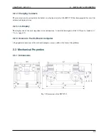
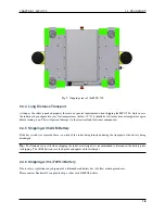
The locations of the basic operating elements of the MPO-700 are shown in the picture below.
2.2.1 Emergency Stop Buttons
When one of these buttons is pressed the robot is immediately set to emergency stop. All drives are disconnected from
power supply. This state can be reset by unlocking the emergency stop buttons and turning the
(page 21)
clockwise to position II for a few seconds.
2.2.2 Key Switch
See
(page 21).
2.2.3 Charging Connector
This connector provides direct, not fuse protected access to the battery. The battery charger can be plugged in here.
Please see the chapter
(page 38) to know more.
11
Содержание MMO-700
Страница 1: ...MMO 700 Neobotix GmbH Apr 14 2022 ...
Страница 11: ...CHAPTER 1 MMO 700 1 6 TRANSPORT Fig 3 Position of the auxiliary batteries and battery connectors 7 ...
Страница 33: ...CHAPTER 3 GENERAL HARDWARE INFORMATION 3 4 CHARGING STATIONS Fig 2 Position of the main power switch X 29 ...
Страница 52: ...CHAPTER 4 OMNI DRIVE MODULE 4 4 ELECTRICAL INSTALLATION Fig 1 Dimensions of the Omni Drive Module 48 ...
Страница 53: ...CHAPTER 4 OMNI DRIVE MODULE 4 4 ELECTRICAL INSTALLATION Fig 2 Bottom view of the Omni Drive Module 49 ...
Страница 54: ...CHAPTER 4 OMNI DRIVE MODULE 4 4 ELECTRICAL INSTALLATION Fig 3 Top view of the Omni Drive Module 50 ...


