background image

Tucker GmbH, 

Mail / Post:

 Max-Eyth-Str.1, 35394 Gießen, Germany


Stud welding unit N800i 
As of 24.08.2021 
Manual part number: BE 1227 

34 


4.2.6 

Connection of the workpiece 

As standard, the earth ground cable is equipped with two earth ground terminals which 

have to be connected to the workpiece. 

When connecting the earth terminals attention must be paid to the following: 

1. 

The earth ground terminals must be connected directly to the workpiece or to the 

workpiece fixture (welding bench, welding grid). 

Steel constructions, tracks, pipelines, etc. may not be used as current conductors, 

unless they are themselves the workpiece to be welded. 

2. 

The welding current circuit may not be earth grounded. 

Exception:  The  workpiece  itself  or  the  workpiece  fixture  are  earth grounded 

compulsorily (pipelines, shipbuilding, etc.). 

  Place the earth ground terminals if possible at the same distance from the point 

of welding when two ground clamps are used. 


Note! 

Prior to connecting the earth ground terminals the following advice on 

avoi- ding any arc blowing must be observed! 


4.3  Arc Blowing Effect 

Blowing  effect  is  the  designation  for  the  lateral  deviation  of  the  arc  from a central 

position. Depending on the cause, a distinction is made  between the following 

blowing effects. 

Thermal blowing effect: 

  Deviation of the arc as a result of the expansion and turbulence  of heated gases 

in the combustion area of the arc. 

Magnetic blowing effect: 

  Deviation of the arc as a result of the influence of magnetic or  electromagnetic 

fields. 

The  possibilities of  reducing  the  thermal blowing  effect are  limited.  They are 

restricted to precise centering of the stud and chuck. 

Содержание N800iTM

Страница 1: ... Mail Post Max Eyth Str 1 35394 Gießen Germany Stud welding unit N800i As of 24 08 2021 Manual part number BE 1227 Stud welding unit N800iTM For Control Board Software 1 06 and higher Operation and Service Manual ...

Страница 2: ...ormity 14 2 Safety at work 15 2 1 Safety Symbols 15 2 2 Safety notices 16 2 3 Intended use 22 2 4 Guarantee and liability 23 2 5 Use of original NELSON spare parts 24 2 6 Copyright 24 3 Delivery and Transport 25 3 1 Extent of delivery 25 3 2 Packing and dispatch 25 3 3 Inspection of incoming materials 25 3 4 Intermediate range 25 3 5 Storage 25 3 6 Transport 25 3 7 Operating Location 26 4 Connecti...

Страница 3: ...set 72 6 13 Demo Mode 72 6 14 Cable Resistance Monitor 72 6 15 Constant Energy 73 6 16 Chuck Change Indicator 74 6 17 Configuring the stud feed interface to act as a Weld Complete signal 74 6 18 F Code F61 Pulse Cleaning Contaminant to be Cleaned 75 6 19 F Code F62 Gun as Remote 75 6 20 Code F63 Pecker Mode 75 6 21 F Code F64 Fieldbus Selection 75 6 22 F Code F65 Weld Complete 24V Signal 75 7 Func...

Страница 4: ...8 2021 Manual part number BE 1227 10 2 Problems Possible Cause Solution 108 10 3 Welding Problems 109 10 4 Wiring Diagram Nelweld N800i 131 11 Annex 132 11 1 Disposal of the Nelweld N800i 132 11 2 Disposal in accordance with the European directive 133 11 3 Abbreviations 134 11 4 Literature 135 ...

Страница 5: ...ation of the Nelweld N800i welding unit can only beguaranteed with knowledge of the contents of these operating and ser vice instructions In case of difficulty or ambiguity please contact the customer service ofNelson which will be very glad to help you The illustrations specifications and technical data in these operating and service instructions are in accordance with the status of 24 01 2012 Ne...

Страница 6: ... it was possible to considerably reduce the dimensions and the weight of the Nelweld N800i The weld currents and weld times required for stud welding can be set stepless on the appropriately display function keys The entire weld cycle is coordinated by the control unit of the Nelweld N800i and can be visually traced by means of the LED display elements Fault messages are issued and numerically cod...

Страница 7: ...weld pool againstatmospheric oxidization and contain the molten liquid metal in order to center the arc In addition to this the molten metal is prevented fromcooling too quickly When welding overhead or in a horizontal position the ceramic ferruleensures that the weld bead always has a constant shape and provides the user with protection against spatter The short cycle method is a variation of the...

Страница 8: ...ssed spring When the welding stud is lifted from the workpiece an pilot arc is drawn to begin with and then the main arc is ignited During the travel motion the arc melts the end of the stud and an ap proximately equally sized area on the workpiece so that a pool of liquid metal is formed under the arc and the stud As soon as the gun coil is switched off circuit the stud accelerates backonto the w...

Страница 9: ...served The weld gun has been set to the studs to be welded in the fac tory The stud type is noted on the type plate of the gun 1 6 Ceramic Ferrules Ceramic ferrules according to EN ISO 13918 are used when welding in keeping with the drawn arc method They form a combustion chamber around the weld which centers the arc and protects the user against welding spatter In addition to this the cooling dow...

Страница 10: ...tions for power transmission c Only for momentary drawn arc procedure d Restrictions for the heat transfer e Up to 10 mm diameter and inert gas Bolt material Basic material ISO TR 15608 Group s 1 and 2 1 ISO TR 15608 Group s 2 2 3 6 ISO TR 15608 Group s 8 and 10 ISO TR 15608 Group s 21 and 22 S23 5 4 6 16 Mo3 Well suitable for any application a Suitable with restrictions b Suitable with restrictio...

Страница 11: ... rolled fine grain structural steel and steel casting of a specified minimum yielding point of 360 N mm ReH 460 N mm Group 2 2 Thermo mechanically rolled fine grain structural steel and steel casting of a specified minimum yielding point ReH 460 N mm Group 3 Hardened and tempered and precipitation hardened steel but no rustproof steel of a specified minimum yielding point ReH 360 N mm 1 ISO TR 156...

Страница 12: ...y 50 60Hz System fusing 32A slow blow Output 32kVA No load voltage 75V ON period 3 Weld sequences for at biggest diameter Drawn arc method max 5 weld min Short cycle method max 60 weld min Weld current range 50 800A Weld time range for Drawn arc method 100ms 1000ms Short cycle method 5ms 100ms Unit fuses F1 F2 1 5A 600V Electronic fusing Protection type due to casing IP23S Protection class 1 one O...

Страница 13: ...Tucker GmbH Mail Post Max Eyth Str 1 35394 Gießen Germany Stud welding unit N800i As of 24 08 2021 Manual part number BE 1227 9 Mains cable H07RN F 4G 6 4x6mm2 Length 3m ...

Страница 14: ...Tucker GmbH Mail Post Max Eyth Str 1 35394 Gießen Germany Top Stud welding unit N800i As of 24 08 2021 Manual part number BE 1227 1 8 1 Dimensions Front Side Rear 10 ...

Страница 15: ...ructions Shielding gas device order no 67 03 04 Weld gun Type NS 40 B 1 B 2 B 3 B 4 complete with accessories see NS 40 B operating instructionsShielding gas device order no 67 03 04 Gas hose pipe 10 m shielding gas hose pipe system Nelweld N800i gun order no 67 07 50 Connecting cable standard Nelweld N800i Workpiece Earth cable H01N2 D with 2 earth holders Cable cross section 2 x 35 mm2 Minimum b...

Страница 16: ... 053 Hardware and Fastener Kit 1 751 585 703a Composite Gun NS 40 FL 67mm 1 751 585 801a Composite Gun NS 20 FL 107mm 1 512 387 056 Ethernet patch cable a Contact Nelson Stud Welding sales representative for availability 1 8 4 Guns cable extension incl control cable Length m Cross section mm2 Part Number Socket inclusive control cable with BIN 4 50 70 7 5 67 01 16 50 67 02 08 70 10 67 03 29 50 67 ...

Страница 17: ...anual part number BE 1227 13 7 5 722 000 165a 722 000 167a 15 722 000 164a 722 000 166a 1 8 5 Mass cable extension Length m Cross section mm2 Part Number Socket 50 70 5 68 03 61 50 BKa 68 03 63 50 BK SKb 68 04 39 70 10 652 23 41 50 67 02 09 70 95 15 67 03 78 50 a BK Socket contact b BK SK Plug contact ...

Страница 18: ......

Страница 19: ...y at work and accident prevention regulations and have a training authorizing them to perform stud welding All persons who work with the unit are obliged to read and observe all the operating and service instructions of the welding unit prior to commencing work In addition the operating instructions of the weld gun connected in each case must be read and observed Danger The addendum means that dea...

Страница 20: ...tions have to be observed Operating instructions must be kept where the Nelweld unit is used The ability to quickly consult the manual is highly recommended to all Nelweld users Safety signs stickers etc must remain attached to the Nelweld unit at all times They should remain free from dirt and be kept in legible condition Personnel training Warning Only a qualified electrician should perform any ...

Страница 21: ...ves as per DIN 4841 Part 4 Helmet as per EN 397 in case of overhead welding Ear protection plugs muffs as per DIN EN 352 is recommended During welding exposed parts of the welding head are current carrying For this reason wear no electrically conductive jewelry wrist watch or chain Protective measures at the workplace The workplace must be such that people in the vicinity are adequately protected ...

Страница 22: ...r people with cardiac pacemakers Attention must be paid to the fact that the welding and earth cable are laid as close together as possible near to the floor and with sufficient clearance to external electrical equipment This is particularly applicable when welding in residential and commercial area as well as on building sites and on special installations If in doubt the user must convince himsel...

Страница 23: ...e for a secure fit of the supply tube system on the screwed in connection Warning During welding certain exposed parts of the weld gun such as the stud and the chuck and all parts electrically connected with this are current carrying Wear no electrically conductive jewelry such as rings watches or chains Safety measures during normal operation Only use the welding unit when in a technically perfec...

Страница 24: ... extremely dry and hot rooms with restricted freedom of movement on electrically conductive parts metallic ladders scaffolding mounting rails floor plates etc In confined conditions between or on electrically conductive parts Under these working conditions the following protective measures must be taken The welder must be adequately protected against electrical dangers by using insulating underlay...

Страница 25: ... IP 23 S Protection against penetration by foreign bodies Ø 12mm Protection against splash water inclined up to 60 to the perpendicular Protection class I Unit with basic insulation and connection of all exposed conductive parts to the protective conductor WARNING During wet weather e g rain with the N800i should not be welded outdoors Wet equipment must dry out before use Operators must always us...

Страница 26: ...agnetic disturbance must be expected in external electrical equipment as a condition of its process The operating location of the Nelweld N800i is limited to areasof an industrial and trading nature When used in residential and commercial areas the user of the system must ensure that the electromagnetic fields that occur during welding do not cause any dangers to persons and property The Nelweld N...

Страница 27: ...g unit Non compliance with the operating instructions of the Nelweldunit and associated options Non compliance with the operating instructions for the systemcomponents Use in moist inflammable and potentially explosive surroundings Use in residential and commercial areas as well as in businessestablishments Improper start up maintenance and conversion of the weldinghead Start up in case of imprope...

Страница 28: ...ts provided they havebeen professionally installed or converted We can also only admit claims arising from the Product Liability Act if original spare parts have been used Please pay attention to the exclusive use of original NELSON spare parts not only for warranty and liability reasons but also to ensure thecorrect operation of our products 2 6 Copyright The contents of the documentation are pro...

Страница 29: ...e checked for damage as well as for the completeness of the parts within the extent of delivery Any possible transport damage and or missing parts have to be immediately made known to the manufacturer or the authorized forwarding company 3 4 Intermediate range If the Nelson N800i welding unit is not operated immediately after delivery it must be put into intermediate storage in a secure place The ...

Страница 30: ... off and clearly marked with warning and informatory signs Inflammable and explosive materials must be removed from thedanger zone Note We expressly point out that welding in commercial areas in the open or in open halls is as a general principle forbidden Danger Wearers of cardiac pacemakers are as a general principle forbid den to stay in the vicinity of stud welding facilities Electrical extern...

Страница 31: ... 24 08 2021 Manual part number BE 1227 27 Warning In keeping with standard EN 60974 10 the welding unit N800i is sui ted for use in an industrial environment limit class A We expressely point out that units of limit class A can cause radio interference in residential and commercial areas ...

Страница 32: ...ion lines should be installed as faras possible without loops The Nelweld N800i must be adequately protected against the intrusionof liquids It may not be installed on liquid bearing pipelines In order to guarantee unimpeded temperature exchange with the environment a minimum clearance of 1 m to existing heat sources must beobserved Attention must be paid to the fact that the ventilation slits on ...

Страница 33: ...ignation Description 1 X3 Welding cable connection 2 X2 Welding cable connection 3 Gun Gas connection Outpu 4 Bottle Gas connection intput 5 X1 Control Cable connection 6 Mains cable connection Warning Prior to any connection work the Nelweld N800i welding unit must be switched off The mains switch of the unit must be in the 0 position ...

Страница 34: ...used In order to electrically protect the welding system against shortcircuits a 32A back per phase with slow response characteristicsis required Once these criteria have been met the switched off welding unit can beconnected to the supply voltage with due regard to the safety advice Warning Connection to the mains may only be carried out by an electrical specialist Before connecting ensure that t...

Страница 35: ...he welding cable plug of the gun to the welding cable socket of the N800i The connection must be secured by a full turn to the right of the welding cable plug 4 2 3 Connection of the Control Cable The control cable socket serves to take the control cable plug of the gun The signals to control the gun are transmitted via the control cable In keeping with the weld gun to be connected type NS 40 B or...

Страница 36: ... full turn to the right of the earth ground cable plug 4 2 5 Connection of the shielding gas Prerequisites The Nelweld N800i has an optional shielding gase valve combination kit that can be factory or feild installed The connected weld gun has already been equipped with the optional special equipment for shielding gas Standard Mode When the gun with manual stud loading is connected the tubes from ...

Страница 37: ...s of the marked coupler plug The tubing system with coupler socket optional must be pushed into the coupler plug to lock it into place Connection of the gun Symbol Connection The tubing system to the weld gun or to the feeder must be connected to the coupler socket The tubing system with coupler plug optional must be pushed into the coupler socket to lock it into place Should the gas tubes be remo...

Страница 38: ... or the workpiece fixture are earthgrounded compulsorily pipelines shipbuilding etc Place the earth ground terminals if possible at the same distance from the point of welding when two ground clamps are used Note Prior to connecting the earth ground terminals the following advice on avoi ding any arc blowing must be observed 4 3 Arc Blowing Effect Blowing effect is the designation for the lateral ...

Страница 39: ...o the point of welding In the event of a one sided earth terminal the arc blows away from the terminal The condition can be eliminated by additional metal plates Influences upon the arc as a result of welding cable itself can largely be avoided by turning the weld gun through 90 When welding sections arc blowing can be reduced by repositioning the earth terminal and additional metal plates Note Th...

Страница 40: ...Tucker GmbH Mail Post Max Eyth Str 1 35394 Gießen Germany Stud welding unit N800i As of 24 08 2021 Manual part number BE 1227 36 4 4 Connection Diagram Short Cycle and Drawn Arc Welding ...

Страница 41: ...Tucker GmbH Mail Post Max Eyth Str 1 35394 Gießen Germany Stud welding unit N800i As of 24 08 2021 Manual part number BE 1227 37 4 5 Connection Diagram Shielding Gas ...

Страница 42: ...essive operating temperatures and nuisance shutdown Keep machine dry Shelter from rain and snow Do not place on wet ground or in puddles Caution DO NOT MOUNT OVER COMBUSTUBLE SURFACES Where there is a combustible surface directly under stationary or fixed electrical equipment that surface shall be covered with a steel plate at least 1 6mm thick which shall extend not less than 150mm beyond the equ...

Страница 43: ...or 460VAC 575V machines are internally connected for 575V from the factory Open the access panel on the rear of the machine POWER CORD CONNECTION A power cord is provided and wired into the machine Follow the power cord connection instructions TROUBLESHOOTING WITH COVER OFF Do not remove plexiglass Unlike other welders N800i heat sinks have HIGH VOLTAGE Caution Incorrect connection may result in e...

Страница 44: ...Tucker GmbH Mail Post Max Eyth Str 1 35394 Gießen Germany Stud welding unit N800i As of 24 08 2021 Manual part number BE 1227 40 5 Control and Display Elements 5 1 Front Panel Controls and Displays ...

Страница 45: ...the machine I ON 0 OFF Upon powering up the internal control software per forms a series of diagnostic tests to ensure correct connection and operation of the power source 8 Weld Time Stud Ex pert Display Material Display The TIME setting is displayed on the front panel LOWER display It can be changed using the Up Down arrow keys to the right of the time display in one 1 ms increments 9 Warning al...

Страница 46: ...Tucker GmbH Mail Post Max Eyth Str 1 35394 Gießen Germany Stud welding unit N800i As of 24 08 2021 Manual part number BE 1227 42 Weld Tool Icon ...

Страница 47: ...ith a stainless wire brush or scra per 5 Take care that the workpiece is stored free from vibrations parti cularly important in case of large and thin walled workpieces 6 Chlorous solvents must by all means be removed from the wel ding zone They may not be exposed to the arc radiation 7 Poor welding quality as a result of arc blow can be avoided by careful grounding techniques such as using multip...

Страница 48: ...el section and up down buttons 4 to adjust time and current discretely 2 Push Stud Expert TM Mode button 2 in the Front Panel section and up down buttons 4 to adjust stud diameter and weld position or another process condition and the welder automatically sets the weld current and time using a database 3 Push one of the 10 preset buttons 5 in the Front Panel section to choose one of the factory pr...

Страница 49: ... pulled it means the rated duty cycle is exceeded during operation It is advised to check the value of F2 and possibly reduce the value of F2 to reduce the on time and increase the studs per minute without cold plunge In normal operating modes the desired setting and the actual current will be the same In this situation the display does not change during or after a weld However in conditions where...

Страница 50: ...at 2mm lift and below 2 The plunge also needs to be appropiately set 3 When the E009 error appears the lift and plunge should be reviewed 4 If the error is E004 or E007 it generally means no pilot arc 5 Check input voltage from unit control panel using F18 and read capacitor voltage 6 If the lift capability is marginal i e it lifts a low lift height but fails to lift at slightly higher lift height...

Страница 51: ...d by the desired custom values When the orange LED of the preset button being pressed turns ON the selected preset has been successfully programmed Note The weld parameter presets depends on to choosen weld method short cycle drawn arc 6 3 6 Recommended Weld Parameters The values specified in the tables and diagrams respectively must be seen merely as guide values which were achieved under optimiz...

Страница 52: ...rs in the tables and in Stud Expert are provided as is without warranty of any kind either expressed or implied including but not limited to the implied warranties of merchantability and fitness for a particular application Performance suitability for any specific application should be determined by the user The user assu mes all liability of the use or the results of the use of the recommended we...

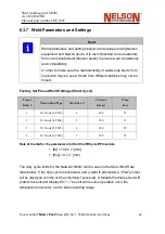
Страница 53: ...s may not be mixed Factory Set Preset Weld Settings Short Cycle Preset Bank 2 Nelson Stud Type Stud Size Current Amps Time ms 1 SC Studs 3 0 M3 4 400 15 2 SC Studs 4 0 M4 5 500 15 3 SC Studs 5 0 M5 6 600 20 4 SC Studs 6 0 M6 7 700 25 Rule of thumb for the parameters for the Short Cycle Procedure I A 100 x mm t ms 4 x mm The duty cycle limits for the Nelweld N800i can be seen in the Stud Weld Rate ...

Страница 54: ...10 S8 8 550 300 7 MP F M10 9 650 300 8 SD10 MR M12 S10 10 750 350 Estimated values for the parameters for the Drawn Arc Procedure1 I A 80 x mm t ms 20 x mm Prest bank 0 or 1 are loaded such that presets 0 8 are as described above when in drawn arc mode Note The preset bank may be selected manually using Function Code F44 1 This estimated values are taken from the standard DIN EN ISO 14555 ʺArc wel...

Страница 55: ...300 1 0 1 5 2 0 2 5 32 MR M10 S8 8 550 300 1 0 1 5 2 0 2 5 32 MP F M10 9 700 350 1 0 2 0 2 5 3 0 28 SD10 MR M12 S10 10 750 400 1 5 2 0 2 5 3 0 25 Estimated values for the parameters for the Drawn Arc Procedure1 I A 80 x mm t ms 20 x mm The weld rates assume an additional 0 08 sec power on time beyond the weld time during stud plunge Stud loading and unloading time are not taken into consideration ...

Страница 56: ...ot appearin the list for selection Short cycle mode F30 If configured for short cycle mode studs requiring 100ms will not display in the list Conversely in drawn arc mode studs requiring 100ms will not display in the list lstandard tstandard laluminium taluminium Process 3mm Pitch Base 200 100 100 160 Drawn Arc 3mm Full Base 220 100 110 170 Drawn Arc 3mm IS Bolzen 200 150 200 150 Drawn Arc 3mm SC ...

Страница 57: ...16ʺ Pitch Base 440 230 240 390 Drawn Arc 5 16ʺ Full Base 490 260 270 450 Drawn Arc 8mm Pitch Base 440 230 240 400 Drawn Arc 8mm Full Base 500 270 270 460 Drawn Arc 8mm MR M10 S8 550 300 550 300 Drawn Arc 8mm SC Bolzen M8 700 25 700 25 Short Cycle 8mm WTOP M8 1250 80 1250 80 Short Cycle 8mm ATC M8 920 80 920 80 Short Cycle 3 8ʺ Pitch Base 530 290 280 500 Drawn Arc 3 8ʺ Full Base 600 330 320 580 Dra...

Страница 58: ...00 460 920 Drawn Arc 15mm Pitch Base 890 510 480 960 Drawn Arc 15mm Full Base 1030 610 550 1160 Drawn Arc 5 8ʺ Pitch Base 960 560 510 1050 Drawn Arc 5 8ʺ Full Base 1110 660 590 1270 Drawn Arc 16mm Pitch Base 970 560 520 1060 Drawn Arc 16mm Full Base 1120 670 600 1280 Drawn Arc 16mm S16 SD16 1400 550 1400 550 Drawn Arc 17mm Pitch Base 1050 610 560 1170 Drawn Arc 17mm Full Base 1220 730 650 1420 Dra...

Страница 59: ...e gun trigger for a few seconds Isolate the gun so as not to start weld Pull and hold down the trigger The gun will lift and release for the programmed weld time Continue holding the trigger for 2 more seconds The gun will lift for 2 seconds then release During the 2 seconds a manual measurement may be taken Warning Press the gun against an insulated solid surface Do not do air trigger as lift che...

Страница 60: ...rmany Meter feet Stud welding unit N800i As of 24 08 2021 Manual part number BE 1227 6 4 Rating Charts 6 4 1 Maximum Weld Cable Length1 Maximum Weld Cable Length Nelweld 800i 1 Check with Nelson representative for a Weld Cable Length calculator 57 Ampere ...

Страница 61: ... function to measure configure the drop time of the gun While viewing this function that is with F31 on the display attempt a weld The gun will lift and drop but no weld current will pass The gun s drop time is measured stored displayed and used in weld timing as will be describedlater in this document F2 Plunge short circuit on time This is the time that the weldcurrent remains on after the stud ...

Страница 62: ...the workpiece Under normal conditions it will be equivalent to the Front Panel Time This time measurement is reported after the weld is complete For example Front Panel Time 50ms Drop Time F31 20ms Plunge short circuit on time F2 50ms The weld profile would look like this The resulting Actual Weld Time is 50 ms The main current would be on for the Front Panel Time Plunge short circuit on time F2 5...

Страница 63: ...s done by releasing the gun coil during the pilotarc stage For example Front Panel Time 20ms Drop Time F31 30ms Plunge short circuit on time F2 50ms Since 20ms 30ms 0 the the gun coil is released prior to starting themain current So the weld profile would look like this The resulting Actual Weld Time is 20ms The stud would still take 30ms to drop but the main current and main arc would only be 20m...

Страница 64: ... the rate of stud travel speed in the downward direction Dampeners can adjust this rate for up toa few hundred milliseconds of travel time Temperature As temperatures rise dampeners have less of an impact They allowthe stud to fall nearly 65 faster at 90 degrees F than at 0 degrees F Molten Stud Shape As the stud melts during the weld it has the potential to change shape It may elongate or even dr...

Страница 65: ...ring Standard work testing For welding according to the drawn arc and short cycle method tenstuds must be welded and the following tests carried out on them Visual inspection all studs1 Bending test 5 studs Macro section 2 studs The test results must be documented and attached to the quality docu mentation Simplified work testing In order to check the setting and functionality of the unit three st...

Страница 66: ...nts are not met a bending or tension test must be car ried out on the three previous and on the three subsequent welds The test results must be recorded in the production log Attention It must be noted that the welding work may only be continued when the test results are satisfactory 1 See the following pages for information on visual inspection ...

Страница 67: ...ptipn 1 Perfect weld Even flash weld ring no perceptible errors Corrective measures Not necessary No alteration to the electrical and mechanical parameters 2 Faulty weld Cross section not fully welded Corrective measures Increase weld current and or weld time possibly change polarity 3 Faulty weld Large uneven bead Corrective measures Reduce weld time 4 Faulty weld Pores in flash weld Corrective m...

Страница 68: ...ive measures Not necessary No altera tion to the electrical and mechanical parameters 2 Faulty weld Constriction of the weld stud too long Corrective measures Increase plunge distance check lift check centring of the ceramic ferrule Decrease weld current and or weld time 3 Faulty weld Feebly formed uneven flash weld with a dull surface Stud too long Corrective measures Increase weld time and weld ...

Страница 69: ...tion permanently as record keeping contact Nelson for Nelware PC software 6 8 2 Set up weld monitor tolerance Two tolerances must be configured F34 gun drop time tolerance and F35 weld energy tolerance F34 sets up a time tolerance in milliseconds For example if F34 is set to 10ms it means the actual drop time can deviate from the target by 10ms and the weld is still considered good weld F35 is a p...

Страница 70: ... F33 The welder will flash weld error after seeing a NIO weld and no more welding can be performed thereafter until the user enters a password The password is the same as in Lock mode 2 or 3 F19 and default password is 123456 Once entering the password welding can resume even though the red triangle icon is still flashing It is not necessary to try to clear the error E013 Weld Out of Tolerance bef...

Страница 71: ...on F19 determines how the unit responds to the LOCK key when in the Time Current mode or Stud Expert mode It lets the user configure the level of security as required for the circumstances Lock Mode 1 This is the minimal security mode whereby the user may lock or unlock the panel by simply pressing the LOCK key in the Time Current mode or Stud Expert mode This is the default mode and is intended t...

Страница 72: ...t circuit In some applications it is desirable to set a cur rent level different than the main arc current during plunge For theseapplications enable F46 to use a different current level Then set the plunge current level using F47 Potential benefits are reduced cable and connector heating which reduces down time for production energy savings and providing fine tuning for spatter splatter reduction...

Страница 73: ... benefits are the ability to cut through mill scale galvanized or contaminated workpiece surface more arc stiffness and directional control in corner angle iron or out of position and reduced heat inputwith less backside marking Four parameters are needed to configure square wave pulse welding peak current peak time background current and background time Pulse welding is enabled by enabling F49 Th...

Страница 74: ...s are the ability to pre clean the workpiece from surface oxide stamping oil contamination in sheet metal or thick or varying galvanized surface or mill scaled plate in fabrication or shipyard plates coated with weld able primer Pulse cleaning is enabled by enabling F37 For the peak pulse it att empts to go the maximum rated current for 4ms with a 10ms pause orlow pilot current in between Due to t...

Страница 75: ...ll factory defaults even if theunit was previously locked 6 13 Demo Mode In demo mode the welder will continuously flash all the lights in sequence on the front panel and key features of the welder will be scrolled in the 7 segment displays To enter or exit the demo press 1 2 and3 simultaneously Prior to welding it is recommended that the welderis turned off then back on after using Demo mode 6 14...

Страница 76: ...sate for lift height variation flux load size and protrusion variation zinc coating thickness variation oil or oxide sur face contamination or clean and primer coated surface with the same welding procedure To use this function Set a time and current preset with desired parameters Perform a good weld Store a target using F32 Enable F60 constant power Perform a weld Weld time will be adaptively adj...

Страница 77: ...to act as a Weld Complete signal Use v1 06 firmware or later Make F12 ON Make F54 OFF One time only Before powering on unit press and hold the fol lowing buttons I t mode 1 5 and 0 through boot up If dis play reads OFF release keys turn power off and do procedureagain Otherwise it reads ON and unit is configured appropri ately Doing this configures it to not give the output signal if any errors or...

Страница 78: ... F63 has a value range of 0 to 20 The default is set to 0 This function is used to increase the number of pecks to perform a series of lift plunge actions prior to the weld The inverter will attempt a weld as soon as it detects contact between the stud and work piece or after the number pecks is performed When set to 0 this F Code is disabled 6 21 F Code F64 Fieldbus Selection F64 has values of OF...

Страница 79: ...in the table below The table below is for firmware version 1 05 only F code Description Possible Values Default Unit Notes F0 Language ENGLISH GERMAN ITALIAN SPANISH FRENCH ENGLISH x F1 Error Display E to E018 E x See below for error defines F2 Plunge short circuit on time 0 to 150 100 ms When short cycle mode is enabled this defaults to 20ms When disabled this defaults to 100ms F3 Stud Expert Mod...

Страница 80: ...ILD STEEL F6 Stud Expert Mode process STUD WELD STUD WELD x F7 Calibration Values 700 to 850 750 Clock cycles Used by manufacturing Do not change F8 Chuck Saver OFF ON ON x F9 Gas Enable OFF ON OFF x F10 Gas pre flow time 10 to 2000 500 ms F11 Gas post flow time 10 to 2000 500 ms F12 Stud feed enable OFF ON OFF x This automatically turns on short cycle mode Disabling it does not disable short cycl...

Страница 81: ...feed is enabled F15 Stud feed style AFTER CON TACT BREAK AFTER WELD AFTER CONTACT BREAK x When to get the signal This only applies when stud feed is enabled F16 Stud feed on air trigger OFF ON OFF x To feed a stud even when triggering the gun while not welding This only applies when stud feed is enabled F17 Loadbank enable OFF ON OFF x For manufacturing This is a read only function used for burn i...

Страница 82: ...ck again It will prompt for the same password entered when originally locked Pass word can be up to 9 characters Mode 3 Same as mode 2 except user can tog gle between presets and cannot change the value of presets Mode 4 Same as mode 3 except the user can adjust the time and current by a percentage as set by F57 F20 Debug ENTER DEBUG MODE ENTER DEBUG MODE x Used by manufacturing and service F21 Us...

Страница 83: ... TON HOLD TIME DOWN BUT TON x While in this F code press and hold the time down button to reset all F codes to default F27 Scroll Speed 100 to 500 150 ms Controls text scrolling speed F28 Pilot Arc Extension 0 to 10 0 ms This is the time the control will wait to start the main arc after establishing a stable pilot arc F29 Chuck Change Counter OFF to 1000000 OFF Welds Increments by 1000 Press down ...

Страница 84: ...overridden by using the arrow keys This value changes to 7ms when short cycle mode is enabled 12ms when disabled This value changes automati cally depending on F30 short cycle mode and the gun interface installed in the unit F32 Weld Results I Current Amps V Voltage Volts tM Main current time ms E Energy Joules tD Drop Time ms tP Pilot Time ms Pass Fail indicator Cable Resistance mΩ NA X This F co...

Страница 85: ...e tolerance allowed from target weld drop time for deter mining good bad weld F35 Weld Energy Tolerance 1 to 20 10 This defines the tolerance allowed from target weld drop time for deter mining good bad weld F36 Process Monitor Error code on failed weld OFF ON OFF X When enabled an error code is given when the weld is out of tolerance F37 Pulse Cleaning Enable OFF ON OFF X When enabled the weld cu...

Страница 86: ...ed welds Hold the time down arrow to reset F43 Diagnostic Data Phases PWM AVG ABORT code Capacitor imbalance or Duty Cycle Phases X This gives extra diagnostic data after each weld If the power unit is at the maximum output in voltage and current PWM AVG will be 100 F44 Preset Bank 0 to 3 1 X This determines which preset the 0 9 buttons are accessing By selecting the preset bank up to 40 presets c...

Страница 87: ...ime func tion is the only way to configure the drop time In Auto mode F31 automa tically gets a new value taken from the first weld done after power up and af ter the gun is unplugged In Average mode the average of the last 10 welds drop times are used and displayed in F31 F49 Pulse Weld Enable OFF ON OFF Bool Enable this to use pulse welding where the main current pulses to a high and low current...

Страница 88: ...passes 20ms in short cycle mode F54 Near Maximum Output Warning Enable OFF ON OFF X Enable this to throw an error code E015 when the unit is near the maximum output power capability 95 F55 Cable Connector Monitor Enable OFF ON OFF X Enable this to compare each weld s ca ble drop to a target value To save a target value press the LOCK key while viewing this function Do this after making a weld F56 ...

Страница 89: ...to be cleaned Zinc or Galva nized to Primer Paint Oil or Oxide Primer Paint X Use this function to designate how the pulse cleaning function determines ab orts pulsing and begins the main arc Select Zinc Galvanized to start the main arc when sensed voltage is above the threshold set in F38 F62 Gun as Remote OFF ON OFF X Enable this to make the gun select pre sets based on the gun trigger as an in ...

Страница 90: ...ap propriate fieldbus selection to deter mine the IO map and sequence of signals For standard mode disable this F code F65 Weld Complete 24V Signal OFF ON OFF For automated systems this output signal is given after each weld to indicate that the weld was successful The Signal is 24VDC unregulated active high 500ms long F66 Diagnostic Mode 0 to 4 0 X Factory use only 7 To enter exit demo mode press...

Страница 91: ...See troubleshooting E002 BROWNOUT CONDI TION CHECK PRIMA RY VOLTAGE The input voltage dipped low enough to drop out au xiliary supplies Welding is stopped until power is res tored so as to prevent inter nal damage Brown out on input power line See troubleshooting E003 CAPACITOR VOL TAGE IMBALANCE The capacitors could not be balanced for some unknown reason The difference between the caps is greate...

Страница 92: ...the voltage skyrockets after closing relays x Input voltage is too high See troubleshooting E007 INPUT VOLTAGE TO LOW FLIP SWITCH TO CORRECT VOLTAGE SETTING On boot up only after clo sing the charge relay the caps have 10 seconds to get the proper voltage x Incorrect voltage setting or broken bad V F signal from one or more switch boards See troubleshooting E008 PRIMARY OVERCUR RENT ERROR A primar...

Страница 93: ...ort circuit was detected for at least 100ms the weld aborts to protect the power unit Check the gun lift setting Under normal welding conditions this should not hap pen See troubleshooting E013 WELD FAILED OUT OF TOLERANCE The last weld was out of to lerance from the target weld by weld energy or drop ti me Compare actual time current voltage and drop time to find cause A new target can also be se...

Страница 94: ...d to in form the user If the output voltage is at the maximum due to long or small cables high lift the actual current may start to drop below the desired current This war ning can be disabled using F54 Small weld cable long weld cable See troubleshooting E016 WARNING _ CHECK WELD CABLES AND CONNECTORS PRESS LOCK TO CLEAR The measured cable con nector voltage drop was out of tolerance from the tar...

Страница 95: ...ime F31 and the front panel time make it such that the pilot arc supply must be on for more than 40ms The maximum time the pilot arc will stay on is 40ms so it is possible the arc will go out before the main arc starts For consistent welds recon figure the drop time and or front panel time to satisfy the equation F code Front panel configuration E019 ADDITIONAL WAR NING WAIT ON UP PER DISPLAY AND ...

Страница 96: ... weld time F30 Short Cycle Mode OFF 12ms 20ms 1 Drawn Arc Metric Values 1000ms 100ms Limits Stud Expert studs Limits presets to 100ms min weld time F12 Sud Feed Enable ON ON 2 Wire Gun Interfaces Action Result F31 Drop TIme F2 Plunge Short Circuit On Time F44 Preset Bank F30 Short Cycle Enable weld max weld min Other Notes F30 Short Cycle Mode ON 35ms 20ms 2 Short Cycle Values 100ms 5ms Limits Stu...

Страница 97: ...ent and time settings are being used Reduce the current setting and perform weld inspections as described in Sections 2 7 4 and 2 7 5 Plunge is too short Plunge is measured by the amount of stud protruding beyond the bottom edge of the ferrule Consult Section 2 6 to ensure proper plunge settings are being used and correct if necessary Incorrect ferrule Ensure that the ferrule being used in the wel...

Страница 98: ...r ferrule for the stud size and application Inconsistent gun lift Perform a Lift Check as specified in Section 4 5 14 Consult Section 2 6 to ensure proper lift settings are being used Correct the lift to the proper setting if the lift is improperly set Perform weld inspections as described in Sections 2 7 4 and 2 7 5 Inconsistent gun lift Perform a Lift Check as specified in Section 4 5 14 several...

Страница 99: ...If the stud is off center it can restrict the plunging motion of the stud during welding Time setting or current setting is too high Check the stud burn off If the burn off is much greater than what is typical for that diameter stud the time and current settings may not be correct Consult Section 2 6 to ensure proper current and time settings are being used Correct the settings and perform weld in...

Страница 100: ...late or stud may cause the arc to become erratic Ensure that the re is no rust scale oil water residue paint galvanization etc present between the stud and the work piece Welding to a clean plate can help diagnose if there is any foreign substance on the base material or studs Incorrect ferrule Ensure that the ferrule being used is the proper ferrule for the stud size and application ...

Страница 101: ...orks best Neither aggressive or alcoholic agents nor combustible liquidsmay be used for the cleaning work The unit casing of the Nelweld N800i must be wiped down witha dry cloth Type plate and safety advice must be very legible The front plate of the Nelweld N800i must be cleaned with a fat dissolving cleansing agent The LED display elements must be recognisable The electrical connecting cables mu...

Страница 102: ...cting input connector 2 Keeping the machine clean will result in cooler operation and higher reliability Be sure to clean the following areas with a low pressure air stream See figure D 1 for component locations Power and control printed circuit boards Power switch Input rectifier Heat sink fins Warning Heatsinks can stand under tension and or be hot Output terminals Examine capacitors for leakage...

Страница 103: ...Stud welding unit N800i As of 24 08 2021 Manual part number BE 1227 Tucker GmbH Mail Post Max Eyth Str 1 35394 Gießen Germany 100 9 Drawings and parts lists 9 1 Explosion drawing Final Assembly N800i ...

Страница 104: ... 00 CE FILTER PCB ASSEMBLY 18 6 524 005 210 M4 KEPS NUT SS CONTROL PCB COVER GROUND FRONT PANEL GROUND MOUNTING 19 5 524 005 273 M6 KEPS NUT SS VERTICAL PANEL CONTROL BD BRACKET INPUT CABLE GROUND MOUNTING 20 2 524 005 278 M4x25 SHCS SS VALVE MOUNTING 21 8 524 005 124 M5x12 PHCRMS SS CONNECTOR PANEL MOUNTING 22 8 524 005 256 M5 LOCK WASHER SS CONNECTOR PANEL MOUNTING 23 4 524 005 283 M4x6 PHMS SS ...

Страница 105: ... 1 709 256 014 ROTARY SWITCH POWER 32A NS 1 716 050 002 FERRITE CORE TOROID NS 24 in 103 450 156 TUBING NS 1 723 245 004 HARNESS CONTROL TO LEM TRANSDUCER NS 1 716 050 102 FERRITE CORE CLAMP ON NS 1 723 245 042 HARNESS MAIN SW 3 PHASE BRIDGE INPUT BOARD NS 1 716 050 003 FERRITE CORE TOROID GROUND LEAD NS 1 716 050 101 FERRITE CORE CLAMP ON 9mm CONTROL BD TO DISPLAY BD Comment Sp Spare part Stp Sta...

Страница 106: ...4 N M 35 40 IN Lbs 9 2 1 Parts list cover assembly Item QTY Part Number Comment Description 1 1 750 611 204 COVER 2 1 729 114 200 HANDLE 3 2 524 001 310 WASHER FLAT 3 8ʺ SS 4 2 524 001 323 WASHER LOCK 3 8ʺ SS 5 2 524 001 322 3 8 24 x 3 4 HHCS SS 6 2 724 569 004 DECAL NELSON Comment Sp Spare part Stp Standard part W Wearing part Ssp Stud specific part NS Not shown ...

Страница 107: ...21 Manual part number BE 1227 Tucker GmbH Mail Post Max Eyth Str 1 35394 Gießen Germany 104 7 9 1 8 6 10 2 4 13 5 Air Flow Direction 12 13 11 3 9 3 Chassis Sub ASM Note Rotate strain relief 30 degrees clockwise to have access to the screws ...

Страница 108: ...14 074 011 CABLE GLAND NUT 6 4 524 005 279 M4x16 PHMS SS FAN MOUNTING 7 4 524 005 284 M4 FENDER WASHER SS FAN MOUNTING 8 5 524 005 210 M4 KEPS NUT SS FAN CHASSIS GROUNDMOUNTING 9 4 717 140 010 GROMMET RUBBER FAN MOUNTING 10 1 524 005 273 M6 KEPS NUT CHASSIS GROUND MOUNTING 11 1 524 005 010 M4 INTERNAL TOOTH WASHER CHASSISGROUND MOUNTING 12 1 524 005 285 M6 INTERNAL TOOTH WASHER CHASSISGROUND MOUNT...

Страница 109: ...rt number BE 1227 Tucker GmbH Mail Post Max Eyth Str 1 35394 Gießen Germany 106 Dinse Hardware See Note 9 4 Front panel assembly Note Grease connectors by filling groove of rear cap with nyogel 760g or equivalent silicone free gre ase before assembling ...

Страница 110: ...NG QUICK PLUG 3 1 520 001 252 COUPLING QUICK SOCKET 4 2 520 001 320 FITTING FEMALE M6 TUBING x G1 8 6 2 85 10 02 DINSE FEMALE M10 SCREW 7 1 723 245 041 HRNS TRIGGER CONNECTOR 4 WIREBINDER 8 1 714 232 003 COVER CONNNECTOR BINDER 9 2 524 005 271 SCREW M3x12 PHCRMS SS TRIGGERHARNESS MTG NS 1 723 242 015 HRNS OUTPUT BD TO WORK DINSE NS 1 723 242 039 HRNS OUTPUT FILTER CAPACITOR ASM Comment Sp Spare pa...

Страница 111: ...Tucker GmbH Mail Post Max Eyth Str 1 35394 Gießen Germany Stud welding unit N800i As of 24 08 2021 Manual part number BE 1227 9 5 Vertical panel assembly Secondary Side Primary Side 104 ...

Страница 112: ...SEMBLY 12 1 750 610 062 PILOT ARC PCB ASSEMBLY 13 1 723 245 007 AUXILIARY TRANSFORMER ASSEMBLY 14 4 in 727 029 212 EDGE GUARD 15 20 524 005 210 M4 KEPS NUT SS PCB AUX TRANSFORMER MOUNTING 16 2 714 028 002 CABLE GROMMET LARGE 17 2 714 028 001 CABLE GROMMET SMALL 18 1 723 242 021 CURRENT TRANSFORMER SUB ASM 19 2 524 001 340 WASHER RUBBER CT MOUNTING NS 1 723 242 025 HARNESS OUTPUT RECT TO CONTROL NS...

Страница 113: ... NOT remove plexiglass when the power is on This Troubleshooting Guide is provided to help you locate and repair possible machine malfunctions Simply follow the procedure listed below LOCATE PROBLEM SYMPTOM Look under the column labeled PROBLEM SYMPTOMS This column describes possible symptoms that the machine may exhibit Find the listing that best describes the symptom that the machine is exhibiti...

Страница 114: ...N800i As of 24 08 2021 Manual part number BE 1227 107 Note If you do not understand or are unable to perform the Recommended Course of Action safely contact your local Nelson Authorized Field Service Facility Replace Plexiglas after service Note Replace plexiglass after service ...

Страница 115: ... properly sized See rating section of the manual for recommended fuse and breaker size Welding procedure is drawing too much output current or duty cycle is too high Reduce output current duty cycle or both There is internal damage to the power source Contact an Authorized Nelson Field Service Facility Machine will not power up no lights Make certain that the power switch is in the ON position The...

Страница 116: ...ld settings drift or output power is low Make sure the machine settings are correct for the weld process being used Check for loose or faulty welding cables Ifallrecommended misadjustment havebeenchecked andtheproblem persists contact yourlocalNelson AuthorizedField ServiceFacility Poor welding performance Check for loose or faulty welding cables Make sure the machine settings are correct for the ...

Страница 117: ... 10 3 1 E001 Shorted Control Cable Fix Control Cable and or Gun Fatal meaning you have to power down to continue welding No Acknowledge meaning the error will exist as long as the unit is powered on Note welding can continue while the error exists Yes Description The gun drive circuit sensed a current spike of 10A or greater for at least 10us When this condition is sensed the gun drive turns off a...

Страница 118: ...or will be displayed and if welding the weld will stop im mediately 15VDC is located at pins 1 and 11 of JP11 on the control board The error will be futher classified into E002 A or E002 B E002 A The browout occured while the unit was not welding Check the 15VDC power supply on the control board with a meter then trace it back through the system components per below Likely items to check in order ...

Страница 119: ...eck that 15VDC exists at the control board while unit is not welding idle If it does not exist at idle check primary power and replace power supply or aux transformer as necessary Using a scope determine what the voltage dips to during the weld If the voltage did not dip lower than 14 3VDC replace the control board If the voltage is dipping check the primary and secondary of the aux transformer wh...

Страница 120: ... the unit on the high range 400 the primary capacitor bank has the potential to go out of balance such that they are not the same voltage When they are 20VDC out of balance for 10ms the weld will be aborted to protect the power unit When opera ting the unit with very low current and or very little cable load unit will have the most opportunity for this imbalance Use F18 and the arrows to check lef...

Страница 121: ...reason wiring power supply etc This exists as a safety mechanism in case current sensing fails This is most likely caused by the arc actually popping out Likely problems or items to check in order from most likely to least likely 1 Arc actually popped out Check gun lift Try again If it is consistant it is an internal failure 2 Damaged Broken connection from the current sensor See picture below to ...

Страница 122: ... board senses that the current was 150 or higher of the setting while the control to the power system was at the minimum for 15ms it will abort the weld and display this error This will happen if the current sensing failing for any reason wiring power supply etc This exists as a safety mechanism in case current sensing fails Likely problems or items to check in order from most likely to least like...

Страница 123: ...t of voltage to frequency circuit to switch board Each switch board 1 board in the case of the N800i has a pair of wires to provide an open collector signal to the control board These pairs carry a near 15V signal with a frequency in the 3000Hz range that represents the primary voltage The signal is controlled by the switch board which provides an opto coupled linear voltage to frequency signal to...

Страница 124: ...ion from control board to the switch board in V F circuit Check control board JP1 pins 1 9 for one pair 2 10 for the other 4 If the input voltage measures to be correct and the switch boards V F signal can not be calibrated replace the switch board 5 If the V F signal is in a range of 2314Hz and 4529Hz or 250V 470V and when first powered up you still get this error replace the control board ...

Страница 125: ...it 2 Improper adjustment of voltage to frequency circuit to switch board Each switch board has a pair of wires to provide an open collector signal to the control board These pairs carry a near 15V signal with a frequency in the 3000Hz range that represents the primary voltage The signal is controlled by the switch board which provides an optocoupled linear voltage to frequency signal to the contro...

Страница 126: ... Broken connection from control board to the switch board in V F circuit Check control board JP1 pins 1 9 for one pair 2 10 for the other 4 If the input voltage measures to be correct and the switch boards V F signal can not be calibrated replace the switch board 5 If the V F signal is in a range of 2314Hz and 4529Hz or 250V 470V and when first powered up you still get this error replace the contr...

Страница 127: ...d on Note welding can continue while the error exists No Description When a dangerous primary current is sensed by means of the Current transformer sensors in the back of the unit near the fan plenum the control will quickly disable the output of the power section to prevent damage This should only happen due to internal failures Likely problems or items to check in order from most likely to least...

Страница 128: ... a pilot arc If no stud voltage is sensed after 20ms it is assumed that the gun didn t lift and the control throws this error Note If the gun lifts and no arc exists it will try to turn the main current on and will end up with an E004 because no arc exists If the error is consistent check that the work piece is directly clamped to the output of the unit Check for a small burn mark on the work piec...

Страница 129: ...rror exists No Description The voltage to frequency signal as provided by the switch boards to the control board are not within a window defined by the control board indicating that they are invalid or caused by noise on the signal line Likely problems or items to check in order from most likely to least likely 1 Inspect V F wiring from switch board to control board Keep wiring away from high powe...

Страница 130: ...it is ready for more welding The normally closed temperature sensor is located on the output board and connects to pins 1 and 6 of JP3 on the control board The sensor closes when it reaches 80 deg C Likely problems or items to check in order from most likely to least likely Fan is not functional or is blocked Check that fan can physically turn and the wiring to the fan Short the fan sensor to manu...

Страница 131: ...ard 400VDC The unit aborts welds and displays this error if this condition occurs during the main arc time If this occurs during the plunge time the error is not displayed but the weld is aborted as this is expected to happen during plunge time Likely problems or items to check in order from most likely to least likely 1 Gun lift setting is causing too many or too large of material transfers which...

Страница 132: ...e error exists No Description If the unit is configured to compare each weld results Actual current voltage time etc to a given weld target it will display this error when the last weld is out of the configured tolerance range Change weld setup as appropriate set a new target or disable this error as necessary Likely problems or items to check in order from most likely to least likely Change weld ...

Страница 133: ...an continue while the error exists No Description The gun coil was de energized and the stud did not hit the molten pool before current was hut off This lends itself to cold welds Adjustments should be made to the unit settings to avoid this condition Re configure drop time F31 Perform a weld while viewing F31 The unit will measure the new drop time and use it in weld timing Increase the short cir...

Страница 134: ...ering voltage x current it will display this warning When this warning is being displayed there is a possibility that the weld current will start to sag As shown in the picture below if the demanded voltage for any given current is above the diagonal power unit capability line the current will naturally drop in accordance with the capability line For best reliability stay within the Linear Area To...

Страница 135: ...cable resistance target was saved using F55 and F56 upon each weld the unit will measure the weld cable resistance If for any weld the resistance is outside of the tolerance windo set by F56 this warning will be displayed Press the lock key to clear the eroor while viewing the error in F1 error display To remedy periodically tighten connectors and inspect cables for any cause for increased resista...

Страница 136: ...ting a condition where the pilot arc blew out For this condition check surface conditions and clean the work piece of any ferrule dust or debris 10 3 18 E018 Warning Drop Time is too long for Short Cycle Fatal meaning you have to power down to continue welding No Acknowledge meaning the error will exist as long as the unit is powered on Note welding can continue while the error exists No Descripti...

Страница 137: ...le is being exceeded 2 Switch board is out of calibration 3 Switch board malfunctioned If lower display reads CYCLE Check Duty Cycle The N1500I is reated at 9 If lower display reads CAP Step 1 Check Switch Board Calibration Switch boards generate a signal rep resenting the capacitor voltage for the control board Step 2 Switch Board Malfunction If re calibration of the switch board fails exchange t...

Страница 138: ...Tucker GmbH Mail Post Max Eyth Str 1 35394 Gießen Germany Stud welding unit N800i As of 24 08 2021 Manual part number BE 1227 10 4 Wiring Diagram Nelweld N800i 132 ...

Страница 139: ...quirements VER Plastics pure grade Free of bromide compounds No requirements VER Plastics mixed None No requirements HM VER Mercury containing components Undamaged Closed plastic container Hg absorber VER of the mercury LEDs Undamaged Leak proof container HM VER Cable wiring None No requirements VER Gold bearing components None No requirements VER Packing Segregated collection None VER Other mater...

Страница 140: ...th the European directive Only for EU countries Do not dispose of Nelson stud welding units and system componentswith household waste Nelson stud welding units and system components are B2B devices1and therefore exclusively designed for commercial use We expressly point out that Nelson stud welding units and system components must neither be disposed of with household waste nor atmunicipal collect...

Страница 141: ...c Community EMC Electromagneticcompatibility EN European standard ESF Welding stud with an even fore part I A Current in amps IEC International Electrotechnical Commission IEC Norm International Standard IP Protection category code International Protection ISO International Organization for Standardization KrW AbfG Law regarding Waste Recycling and Management KSF Welding stud with tapered for part...

Страница 142: ...es IP Code 2000 EN 60974 1 Arc welding equipment Part 1 Welding power sources 2005 EN 60974 12 Arc welding equipment Part 12 Coupling devices for welding cable 2005 EN ISO 13918 Welding Studs and ceramic ferrules for arc stud welding 1998 EN ISO 14555 Welding Arc stud welding of metallic materials 2006 BGV A3 Accident prevention regulation of the administrative trade association Electrical install...

Отзывы: