Genesis Manual Rev1.6 Copyright 2018, Nellis Engineering, Inc.
6
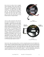
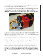
Next, ensure the battery locks are engaged
and the batteries cannot move inside the
body. If the battery assembly was removed,
it will need to be reinstalled in the proper
orientation. The battery packs are slightly
heavier on the side opposite from where the
wires exit. This side should be installed on
the right hand side of the scooter to help
counteract the motor torque when running
(Fig. 3) and the wires from the front of the
scooter should run along the bottom.
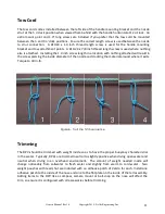
There are three connections inside the DPV
that need to be mated (Fig. 4). First, ensure
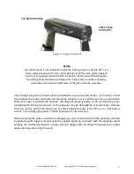
the trigger is locked OFF (small tab rotated
underneath trigger to prevent it from being
depressed) and the speed lever set to the OFF
position (pointing towards the nozzle - Fig. 5)
and then connect the two battery plug sets to
the tail section. You should expect a spark
when the second battery is connected; it is
due to the capacitors in the motor controller
charging. It does not matter which battery is
connected to which plug set on the tail. The
batteries are connected in series, once they
are plugged into the tail section. After the
batteries are connected, plug in the circular
connector, paying attention to the key, which
is towards the center of the tail section and
turn the locking ring clockwise to secure it.
Ensure the o-rings and sealing surfaces are clean and generously greased with Molykote 111
silicone lubricant. Insufficient grease or debris on the sealing surfaces can result in flooding of the
scooter. Install the tail section into the body carefully, ensuring an even gap all the way around
before engaging the o-ring seals. The slot openings for the orange plastic locking strips should be
at 3 and 9 o'clock with the pins of the recharge connector on the nose, pointing up. The slots line
up with the nozzle struts at 3 and 9 o'clock for reference. Install the orange plastic lock strips and
slide the rubber band over the joint. Never grease the grooves used by the lock strips.
Figure 4
Tail section inside view
Figure 3
Battery orientation


