

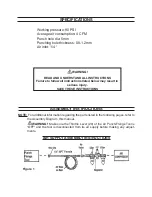


NOTE:
For best service you should incorporate an oiler, regulator, and
in-line filter
(none
of which are included) as shown in
Figure 1.
NOTE:
If you are
not
using an automatic oiler system as shown in
Figure 1,
add a few
drops of pneumatic tool oil (not included) to the airline connection. Add a few drops
after each hour of continual operation.
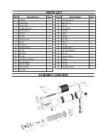
Prepare a 1/4” air connector (not included) by wrapping the threads with plumbers
tape before connecting to the Air Inlet (19) on the bottom of the Air Punch/Flange
Tool. Thread the Air Hose from your compressor to the Air Punch/Flange Tool at
the Air Inlet (19).
Set the air pressure on your compressor to 90 PSI. Do not exceed 90 PSI.
Frequently check the air connections to make sure they remain secure.
2.
3.
4.
OPERATION INSTRUCTIONS
PUNCHING
WARNING: Always wear heavy-duty leather gloves when handling sheet
metal.
Sharp edges can cause severe injury. Always wear ANSI-approved safety
goggles.
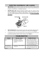
Pre-mark the desired location of each hole you wish to punch on the workpiece.
NOTE:
If the workpiece is to be both punched and
flanged,
flange
it
first,
then measure for
the hole placement. Flanging will change the dimensions of the workpiece.
Connect the Air Punch/Flange Tool to your air supply. Do not exceed 90 PSI.
Insert the edge of the workpiece between the Punch Die (3) and the Punch (6).
Make sure your marks are aligned with the Punch Die (3).
Squeeze the Throttle Lever (20) and the Punch (6) will pierce the workpiece.
Align the tool with the next mark on the workpiece and repeat step 5 until the job
is finished.
Disconnect the air supply.
WARNING: After disconnecting the Air Punch/Flange Tool from the air supply
there could still be enough air pressure to
fire
the Punch/Flange.
After making
sure the air supply is disconnected, ALWAYS
fire
the Punch/Flange repeatedly to
make sure all air is bled from the tool.
1.
2.
3.
4.
5.
6.
7.
8.