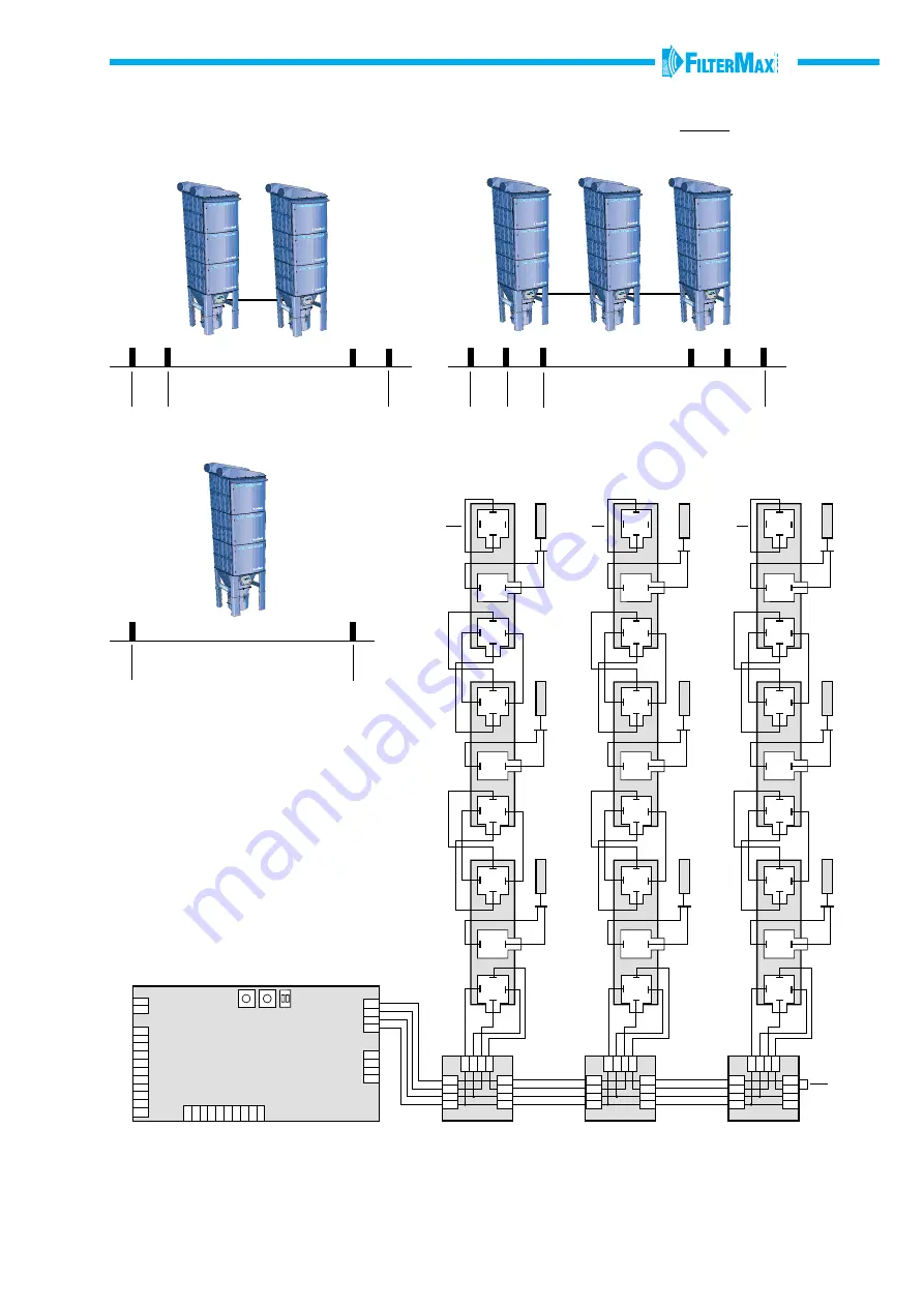
JP1
JP5
S1
S2
S3
JP6
1
2
3
4
5
6
7
8
9
10
11
1
2
3
4
5
6
7
8
9
10
1
2
JP3
230
120
100
0
JP4
-
Door
Pilot
control
IN
OUT
4
3
2
1
1
2
34
1
2
34
1
2
34
1
2
34
4
3
2
1
4
3
2
1
4
3
2
1
1
2
34
1
2
34
IN
OUT
1
2
34
1
2
34
1
2
34
1
2
34
4
3
2
1
4
3
2
1
4
3
2
1
1
2
34
1
2
34
IN
OUT
1
2
34
1
2
34
1
2
34
1
2
34
4
3
2
1
4
3
2
1
4
3
2
1
1
2
34
1
2
34
{
+
15
2 s
2 s
2 s
0
1
0
1
0
1
LINE 3
LINE 2
0
1
0
1
0
1
LINE 1
NB!
LINE 1
LINE 3
LINE 2
Set LINE 1, LINE 2 or LINE 3 with the
0/1-button on the Control Box.
IMPORTANT!
The pilot boxes in line 2 and 3 must
be configurated in the following way:
• Remove the lower protection cover.
• Set the switch on 2 or 3 depending
on what line the pilot box belongs to.
NB! Remove the clamp between 3 and 4
on the output contact before the cable
from the pilot box above is connected.
NB!
NB!
NB!
pause time betweencleanings
pause time between cleanings
pause time between cleanings
Circuit card
FilterMax DX
Control Box
CONNECTION OF SEVERAL FILTERMAX DX TO ONE SYSTEM
Содержание FilterMax DX Series
Страница 36: ...36 INSTALLATION AND SERVICE PROTOCOL 4 Point no Date Note ...
Страница 37: ......


