Fan Inverter
10 Installation
WARNING! Risk of electric shock
Work with electric equipment is to be carried out by a qualified electrician.
WARNING! Risk of personal injury
Before installing the unit, ensure that the input power supply to Fan Inverter is off for at least 5 minutes.
Note
Fill in the information in
Chapter 19 Warranty information
and
.
10.1 Electrical installation
The electrical installation of Fan Inverter is to be done according to the VACON 100 Installation Manual and the
following additional information:
•
Section 22.2 Appendix B: Installation chart
•
Section 22.4 Appendix D: Circuit diagrams
Note
If the STO and ATEX optional board is installed, see the VACON 100 OPTBJ STO and ATEX Option Board
Safety Manual.
CAUTION! Risk of equipment damage
A main switch is to be installed on Fan Inverter power supply. A 4th pole for neutral and a fuse are re-
quired if the same main switch (with a 400 V, 3 phase +N supply) supplies FilterMax or any other 230 V
single-phase equipment. See also
www.nederman.com
.
If the fan is located in a different location from the main switch, a maintenance/safety switch with a signal con-
tact must be installed. The signal contact can be connected to ‘run enable‘, terminals 6 to 9. Then if the switch
is ‘OFF’, Fan Inverter will not start and will also not report “Ready” on relay RO1. Due to the Radio Frequency In-
terference (RFI) emission risk, the switch has to be RFI/EMC protected, and the cable shield must be connected
properly.
Note
When the main and maintenance/safety switch is used as an emergency stop, its handle needs to be red
with a yellow background.
CAUTION! Risk of equipment damage
Use an EMC cable gland at the motor for shielded cable.
10.2 Programming
The unit is preprogrammed for the Fan Inverter application. The Fan Inverter program is also stored in the
keypad memory as a backup. If there is a problem, the unit can be restored to its Fan Inverter default settings
with parameter P6.5.3 in the Parameter backup submenu (M6.5).
The basic parameters, P1.1 to P1.6, for the actual motor have to be set prior to use. See the table in
tion 10.2.1 Quick setup and programming parameters
Note
For a 60 Hz network, set the maximum frequency (parameter: P1.9) to 60 Hz (according to the fan).
WARNING! Risk of personal injury
For Nederman fans, the maximum frequency is the fan nominal frequency, which is either 50 or 60 Hz.
Do not exceed the fan’s nominal frequency since it imposes too much mechanical stress on the impeller.
10.2.1 Quick setup and programming parameters
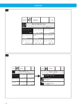
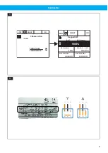
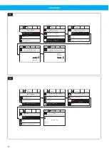
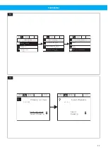
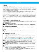
• From the ‘Multimonitor’ page, press the BACK/RESET button to access ‘Main Menu’. See
. Select ‘Quick Setup’ to enter the motor data and maximum frequency according to the fan. See also
tion 12.3 Pressure loss compensation settings
22
Содержание Fan Inverter
Страница 7: ...Fan Inverter B A 5 OK FUNCT BACK RESET 2 3 1 8 6 7 9 4 5 5 6 7 ...
Страница 12: ...Fan Inverter 15 16 12 ...
Страница 61: ...www nederman com ...

