NCF
EN
30
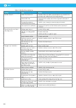
Table 7-1: Malfunctions and causes
Problem
Cause
Solution
Fan does not start
No electrical connection
Check that the motor and/or command inverter is connected to the
electrical power supply line and is correctly powered
Motor malfunction
Check internal connections and motor components and replace if
necessary
No connection between
command inverter and motor
Check for correct connection between inverter and motor
Command inverter malfunction
Check internal inverter circuits and components and replace if
necessary
Power absorption much lower
than design value
Rotation speed too low
Increase rotation speed
Openings or ducting partially
blocked
Eliminate obstruction
Check the position of regulation organs
Impeller partially blocked
Eliminate obstruction
Resistance pressure of system
higher than design value
Check the resistance pressure value of the system
Fluid density lower than
intended value
Check the fluid density value
Too high power absorption
Rotation speed too high
Reduce rotation speed
Resistance pressure of system
lower than design value
Check the resistance pressure value of the system
Incorrect impeller rotation
direction
Check impeller rotation direction and orientation
Pre-rotation of air in opposite
direction to fan rotation
Check minimum installation distances (paragraph 5.1.1) or correct
orientation of intake with pre-distributors
Fluid density higher than
intended value
Check the fluid density value
Power supply to motor with
voltage lower than shown on
identification plate
Check for correct voltage of power supply to motor
Defects in motor windings
Check for correct motor operation
Insufficient pressure
Rotation speed too low
Increase rotation speed
Fluid density lower than
intended value
Check the fluid density value
Air flow greater than intended
value
Check the resistance pressure value of the system
Pulsating operation
Instability of air flow
Check operating field envisaged by operating curve
Fluctuations in flow due to other
fans operating in parallel
Check for correct installation on system
Intake air turbulence created by
system near intake opening
Check minimum installation distances.
Содержание 14550128
Страница 2: ...NCF 2 Declaration of conformity 3 Figures 4 English 9 ...
Страница 6: ...NCF 6 Example of lifting NCF fans 7 Minimum installation distances with inlet duct 8 ...
Страница 8: ...NCF 8 OUTDOOR INSTALLATIONS Leave a bend on the cable to prevent water from entering the motor 11 ...
Страница 31: ...NCF 31 EN ...
Страница 32: ......
Страница 33: ...www nederman com ...

