background image

SMB8000

Issue 3.0

Gigabit PoE Switch Manual

5 - 5

___________________________________________________________________________________

___________________________________________________________________________________

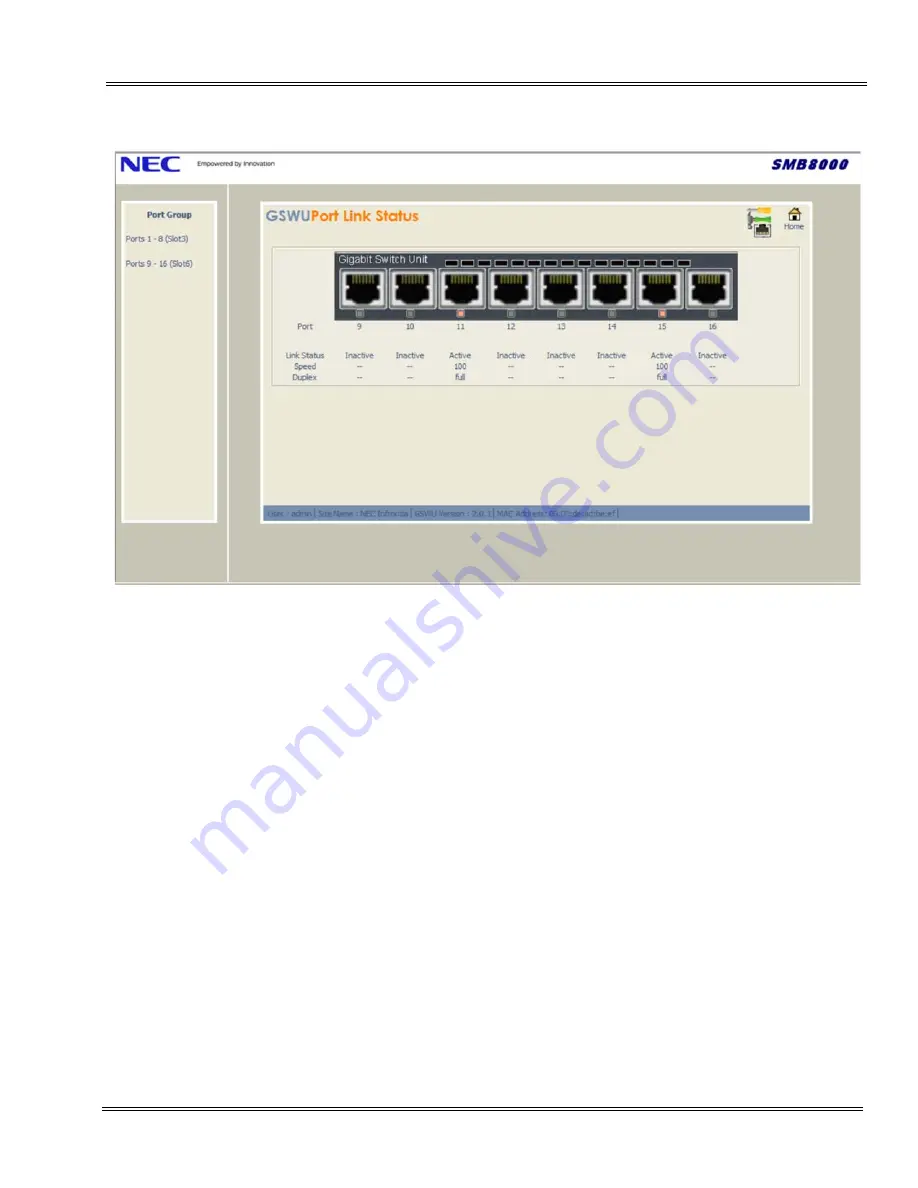
Port – A real time image is displayed for those connected devices. Port LED colors 
are shown  in Green or Red and Gray for those items not connected.

Link Status – Active status indication is shown when there are Ethernet devices 
connected. Inactive is displayed when ports are idle.

Speed/Duplex – When configuring an interface speed and duplex mode, note the 
following:

z

Fast Ethernet (10/100-Mbps) ports support all speed and duplex options.

z

Gigabit Ethernet (10/100/1000-Mbps) ports support all speed options and all 
duplex options (auto, half, and full).

z

Gigabit Ethernet ports operating at 1000 Mbps do not support half-duplex mode.

Figure 5-4  Port Link Status (9~16) Screen

Содержание SMB8000

Страница 1: ...ETIA GIGABIT POE SWITCH MANUAL Issue 3 0 May 2010 SMB8000 ...

Страница 2: ......

Страница 3: ...repared for the use of employees and customers of NEC Unified Solutions and may not be reproduced without prior written approval of NEC Unified Solutions Microsoft and Windows are registered trademarks of Microsoft Corporation Copyright 2010 NEC Unified Solutions Anton Philipsweg 1 1223 KZ Hilversum The Netherlands www nec unified com ...

Страница 4: ......

Страница 5: ...tion 3 Indicators Switches and Connectors 2 4 3 1 LED Indicators 2 4 3 2 Connectors 2 5 3 3 Switches 2 5 3 4 Power and Thermal Considerations 2 5 3 5 Environmental Considerations 2 5 Chapter 3 CD ETIA Blade Setup Section 1 Installing the CD ETIA Blade 3 1 1 1 System Requirements 3 1 1 2 Installation and Safety Precautions 3 1 1 3 Installing the CD ETIA Blade in the Chassis 3 2 Section 2 SV8100 and...

Страница 6: ...abit PoE Switch CD ETIA Blade 5 1 Section 2 Home Menu 5 2 Section 3 Port Link Status 5 4 Section 4 Port Configuration 5 6 Section 5 PoE Settings 5 7 Section 6 Port Mirroring Configuration 5 12 Section 7 Port PVID 5 13 Section 8 VLAN Configuration 5 14 Section 9 Firmware Download 5 16 Section 10 Session Management 5 18 Section 11 Initialization 5 20 Section 12 Configuration Download Upload 5 21 App...

Страница 7: ...4 5 Local Area Connection Properties Screen 4 5 Figure 4 6 Internet Protocol TCP IP Properties Screen 4 6 Figure 5 1 Login Screen 5 1 Figure 5 2 Home Menu 5 2 Figure 5 3 Port Link Status 1 8 Screen 5 4 Figure 5 4 Port Link Status 9 16 Screen 5 5 Figure 5 5 Port Configuration Screen 5 7 Table 5 1 Maximum Power Blades 5 8 Table 5 2 IEEE802 af Class Specifications 5 9 Figure 5 6 PoE Settings 1 8 Scre...

Страница 8: ...__ ___________________________________________________________________________________ Issue 3 0 SMB8000 Figure 5 16 Configuration Download Upload Screen 5 21 Figure 5 17 Save Configuration File to Specific Location 5 22 Figure 5 18 Select File for Configuration Download 5 23 Figure 5 19 System Busy Message 5 23 ...

Страница 9: ...it PoE Switch Manual 1 1 ___________________________________________________________________________________ Chapter 1 Regulatory For regulatory information please refer to the Regulatory Information manual ...

Страница 10: ...2 Regulatory ___________________________________________________________________________________ ___________________________________________________________________________________ Issue 3 0 SMB8000 NOTES ...

Страница 11: ...date a range of workgroup applications This blade provides z Ethernet Ports 8 Gigabit Ethernet 10 100 1000 user ports Status LEDs Indicating Link Speed and Activity User ports source PoE based on the 802 3af standard Auto MDI MDI X Auto automatically detects and corrects crossover cables z Basis Layer 2 Switch Management 802 1Q VLAN Bridging Independent VLAN Learning Support 802 1p Priority Queuin...

Страница 12: ...tem The first three ETIA units can be grouped together to form a single 24 port switch The 4th card should be changed in programming PRG10 55 as Main the following two cards will become Add ons of this card This can be repeated for the 7th and 10th cards giving 4 stacks of three cards If all cards after the third are left as Add ons they will operate in unmanaged mode Unmanaged Switch Functions In...

Страница 13: ...ber determination When a Main board is initialized it assigns the first eight ports as port 1 through 8 When subsequent add on boards broadcast messages are received the CCPU by manual means or any other means will assign a Board Type to the Add on card This will automatically assign its port numbers On power up all ETIA boards are assigned as Main boards or generic Add on boards by no IP address ...

Страница 14: ..._ Issue 3 0 SMB8000 SECTION 3 INDICATORS SWITCHES AND CONNECTORS Refer to Figure 2 1 CD ETIA Blade for LED and switch locations 3 1 LED Indicators The LEDs for each port indicate of the status of an activity Figure 2 1 CD ETIA Blade RJ45 Connector x8 Activity LED x8 LED Display Port Status Solid Green 1000 Mbps Link Solid Yellow 10 100 Mbps Link Off No Link Blinking LED Port Activity ...

Страница 15: ...ed on this blade SW2 4 can be changed from Off to On to reset the blade to the factory defaults 3 4 Power and Thermal Considerations When installing blades be sure to observe system power factor requirements The maximum number of CD ETIA blades that can be installed in one chassis is three For more information refer to the Chassis Power Based Calculator Chart in the SV8100 SV8300 System Hardware M...

Страница 16: ...CD ETIA Blade ___________________________________________________________________________________ ___________________________________________________________________________________ Issue 3 0 SMB8000 NOTES ...

Страница 17: ... jack is specifically designed for wet locations Never touch uninsulated telephone wires or terminals unless the telephone line is disconnected at the network interface Use caution when installing or modifying telephone lines Ground the Controlling and Expansion chassis before installing or removing the blades The Expansion Chassis must be installed with the system power OFF Do not touch the blade...

Страница 18: ...ely into position Tighten the thumb screws on either side of the blade SECTION 2 SV8100 AND SV8300 SYSTEM PROGRAMMING SV8100 System The CD ETIA blade can be programmed using a Multiline Terminal PCPro or WebPro 1 To program the system the CD ETIA blade should be installed in the desired universal slot 2 Access System Programming press Speaker Q Q system password Transfer Figure 3 1 Inserting Blade...

Страница 19: ...nterface 0000 ADMIN1 3 SA System Administrator Level 1 SA 10 01 10 02 10 12 10 13 10 14 10 15 10 16 10 17 10 18 10 22 12 02 12 03 12 04 15 01 15 07 15 09 15 10 15 11 20 16 21 07 21 14 22 04 22 11 25 08 30 03 32 02 40 02 41 02 41 03 41 04 41 05 41 06 41 07 41 08 41 09 41 10 41 11 41 12 41 13 41 14 41 15 41 16 41 17 41 18 90 03 90 04 90 06 90 07 90 18 90 19 9999 ADMIN2 4 SB System Administrator Leve...

Страница 20: ...ETIA Blade Setup ___________________________________________________________________________________ ___________________________________________________________________________________ Issue 3 0 SMB8000 NOTES ...

Страница 21: ...and connecting to default IP address 192 168 1 110 in the browser navigation address bar SECTION 2 CONFIGURING THE PC After the CD ETIA blade is installed in the chassis the PC that is communicating with the CD ETIA blade must be configured to recognize the CD ETIA network address The PC and CD ETIA blade must be connected using a straight ethernet cable and or crossover cable To ensure proper com...

Страница 22: ..._____________________________________________________________ Issue 3 0 SMB8000 To configure the PC 1 Press Start and select Control Panel from the menu Figure 4 1 Selecting Control Panel Windows XP Professional operating system is used in this example When using a different Windows operating system the screens may look slightly different ...

Страница 23: ...____________________________________________________________________________ ___________________________________________________________________________________ 2 On the Control Panel menu double click on Network Connections Figure 4 2 Control Panel Screen ...

Страница 24: ...___________________________________________________________________ Issue 3 0 SMB8000 3 From the Network Connections screen double click on Local Area Connection 4 When the Local Area Connection Status screen is displayed click the Properties button Figure 4 3 Network Connections Screen Figure 4 4 Local Area Connection Status Screen ...

Страница 25: ..._______________________________________________ ___________________________________________________________________________________ 5 From the Local Area Connection Properties screen select Internet Protocol TCP IP and then Properties Figure 4 5 Local Area Connection Properties Screen ...

Страница 26: ...___________________________ Issue 3 0 SMB8000 6 Click on Use the following IP address For this example enter 192 168 1 99 for the IP address and 255 255 255 0 for the Subnet mask Click OK to accept the changes 7 On the Local Area Connection Status screen click Close then close the Network Connections screen by clicking Figure 4 6 Internet Protocol TCP IP Properties Screen ...

Страница 27: ...rosoft Internet Explorer 6 0 or higher is recommended The Login screen allows a user to enter their user name admin and password password for web management access Login as follows 1 Start your Internet Explorer from a PC connected to the same network as the CD ETIA blade 2 Enter the CD ETIA blade default IP Address 192 168 1 110 in the address link of your browser In SV8100 systems the IP Address...

Страница 28: ...u provides access to the configurable settings and administrative functions available for the CD ETIA blade This menu is split into three regions and an informational sidebar Click Refresh if your web page cannot be displayed or to ensure the latest version of the page is displayed The three regions include z Configuration This section of the screen allows access to the following functions z Link ...

Страница 29: ... on page 5 16 and Figure 5 13 Firmware Download Screen on page 5 17 z Configuration Download Upload refer to Figure 5 16 Configuration Download Upload Screen on page 5 21 z Session Management refer to Figure 5 14 Session Management Screen on page 5 19 z Initialize refer to Figure 5 15 Initialization Screen on page 5 20 z Other A logout icon is displayed in this section When pressed the user is log...

Страница 30: ...___________________________________________________________________ Issue 3 0 SMB8000 SECTION 3 PORT LINK STATUS This screen shows the connection status for each Ethernet port This page refreshes automatically every 10 seconds to update the current link status Click Home to return to the Home Menu Figure 5 3 Port Link Status 1 8 Screen ...

Страница 31: ...ose items not connected Link Status Active status indication is shown when there are Ethernet devices connected Inactive is displayed when ports are idle Speed Duplex When configuring an interface speed and duplex mode note the following z Fast Ethernet 10 100 Mbps ports support all speed and duplex options z Gigabit Ethernet 10 100 1000 Mbps ports support all speed options and all duplex options ...

Страница 32: ...rt connection speed can be set only when auto negotiation is disabled Maximum Capability Indicates that the ports speeds and duplex mode setting can be set 10 Half Indicates that the port is advertising 10Mbps half duplex mode setting 10 Full Indicates that the port is advertising 10Mbps full duplex mode setting 100 Half Indicates that the port is advertising 100Mbps half duplex mode setting 100 F...

Страница 33: ...ower demand oversubscribes the remaining available power then the switch prioritizes the power allocating to the ports that present a PD power demand This causes the switch to remove power from one or more lower priority ports to meet the power demand on other higher priority ports This operation occurs regardless of the order in which PDs connect to the switch s PoE configured ports The switch si...

Страница 34: ...ning If the next PD you connect is a class 3 device 15 4 watts max power delivery and is connected to port 3 then power will be removed from the higher numbered port number 5 and be given to the new PD in the lower numbered port 3 However if the PoE power priority is set to High or Critical on port 5 then a new PD plugged to port 3 would not be allowed to power up since lower numbered ports 1 and ...

Страница 35: ...his is reflected by Power Available mW CD ETIA also measures the actual power consumed by each device which may be much less than the maximum for the PoE class and displays this value as Power mW An example using NEC equipment An IP Multiline terminal DT7XX is a class 2 device this will take 7000mW from the total available when plugged in So for a single ETIA in a cabinet this 90 000mW available s...

Страница 36: ...__ ___________________________________________________________________________________ Issue 3 0 SMB8000 Click Apply to accept the changes Click Refresh if your web page cannot be displayed or to ensure the latest version of the page is displayed Click Home to return to the Home Menu Figure 5 6 PoE Settings 1 8 Screen ...

Страница 37: ... PoE Switch Manual 5 11 ___________________________________________________________________________________ ___________________________________________________________________________________ Figure 5 7 PoE Settings 9 16 Screen ...

Страница 38: ...outgoing packets from one port to another port Port Mirroring can be used as a debugging tool Configure the Port Mirroring feature by selecting a specific Port Mirror Traffic to this Port to copy all traffic to be monitored Select the Mirrored port ports Traffic to monitor on Mirror Port Ingress Incoming defines port mirroring on incoming traffic only Egress Outgoing defines port mirroring on outg...

Страница 39: ... provides parameters for managing ports that are part of a VLAN Port defines the CD ETIA port 1 8 included in a VLAN Port PVID Assigns a VLAN ID to untagged or tagged packet Defines the VLAN Port ID to which the table is queried the possible values are 2 4094 Priority Assigns a priority tag to VLAN traffic Possible values are 0 7 Click Apply to accept the changes Click Refresh if your web page can...

Страница 40: ... settings for ports The CD ETIA can be used to connect to other devices that have been configured to use VLANs Typically all VoIP devices are placed in the same VLAN while data devices are placed in a different VLAN Deleting a VLAN Clicking the Delete button deletes the currently highlighted VLAN shown in the Existing VLAN table Status Icons z Blue icon untagged denotes that packets are untagged z...

Страница 41: ..._________________________________________ Add Modify VLAN Designate the new VLAN ID Adding new VLAN ID This is to ensure priority treatment of the VoIP traffic by the system Click OK to confirm Click Refresh if your web page cannot be displayed or to ensure the latest version of the page is displayed Click Home to return to the Home Menu Figure 5 11 VLAN Configuration Screen ...

Страница 42: ...NLOAD The software package on the CD ETIA can be upgraded via the web browser When browse is selected you are prompted to enter the path name where the software package is located Once you have browsed for the file select Send Selecting the cancel button will omit all actions Click Home to return to the Home Menu This firmware is provided by NEC and must be stored locally prior to selecting the se...

Страница 43: ...__________________________________________________________________________________ The firmware update will begin when this window is displayed The window will count down to zero and restart the CD ETIA once the update process is complete Do not power off the system while the upload is in progress Figure 5 13 Firmware Download Screen ...

Страница 44: ...f the currently configured IP Address z Default Gateway Enter the address of the Default Gateway Change Current User z User Name The CD ETIA blade default with one user admin z New Password Enter the new desired password z Old Password Confirm the old password before new information will be accepted Click Apply to accept the changes Click Refresh if your web page cannot be displayed or to ensure t...

Страница 45: ...PoE Switch Manual 5 19 ___________________________________________________________________________________ ___________________________________________________________________________________ Figure 5 14 Session Management Screen ...

Страница 46: ...creen allows users to initialize the NVRAM to the default setting and the allows the CD ETIA blade to be rebooted Reset NVRAM to Defaults When selected will restore factory default setting removing any previously stored information Site name VLANs Port Mirroring etc Reboot ETIA Board When selected will reset and apply any previously stored changes Click Apply to accept the changes Click Home to re...

Страница 47: ..._____ SECTION 12 CONFIGURATION DOWNLOAD UPLOAD This screen allows users to Download restore and or Upload save the ETIA configuration settings Upload Save Configuration File When a user selects Upload he or she is prompted to save the configuration file to a specific location The ETIA configuration file name may be changed but bin extension should not be changed Figure 5 16 Configuration Download ...

Страница 48: ..._________________________________________________________________________________ ___________________________________________________________________________________ Issue 3 0 SMB8000 Figure 5 17 Save Configuration File to Specific Location ...

Страница 49: ...To Download restore the ETIA configuration press Browse to locate the locally stored config bin file Press Download The restoration process is complete once the configuration files is restored and the ETIA automatically reboots During the restoration process a Busy screen is displayed indicating that the process is in progress and that the system must not be powered off Figure 5 18 Select File for...

Страница 50: ...it PoE Switch Web Manager ___________________________________________________________________________________ ___________________________________________________________________________________ Issue 3 0 SMB8000 ...

Страница 51: ... node that serves as an entrance to another network and vice versa Internet The global digital network IP Address A unique address that certain electronic devices use in order to identify and communicate with each other on a computer network utilizing the Internet Protocol standard IP in simpler terms a computer address MAC Address A worldwide unique physical address required for all equipment on ...

Страница 52: ...t Protocol TCP IP Transmission Control Protocol Internet Protocol TCP IP is a networking protocol that provides communication across interconnected networks between computers with diverse hardware architectures and various operating systems VLAN Virtual Local Area Network is a group of hosts with a common set of requirements that communicate as if they were attached to the same wire regardless of ...

Страница 53: ...00 withe NetLink it is recommended to use an external Ethernet switch in place of the CD ETIA for the Secondary systems This is because when NetLink integrates the systems together it performs a slot reset on all Secondary systems this action can cause the Netlink connection to fail and recover in an endless loop due to the loss recovery of the ethernet link There is no problem deploying the CD ET...

Страница 54: ...CD ETIA Limitations ___________________________________________________________________________________ ___________________________________________________________________________________ Issue 3 0 SMB8000 ...

Страница 55: ......

Страница 56: ...Gigabit PoE Switch Manual NEC Unified Solutions Issue 3 0 SMB8000 ...

Отзывы: