background image

The figures in this manual are based on the external view of a standard model.
Consequently, the shape may differ from that of the air conditioner you have selected.

Air Intake

Air Intake

Air Outlet

Air Outlet

Louver

Vertical Adjustment

Louver

Horizontal Adjustment

Air Filter

Remote Controller

Connection Cord

Pipes and Power

Drain Hose

Front Panel

Emergency Panel

Display Panel

Note: Condensate water drains
at COOLING or DRY operation.

Identification of parts

3

Indoor unit

Outdoor unit

Note: The pipes and powe r connection cord will be provided or purchas ed by cust ome r.

PDF created with pdfFactory Pro trial version 

www.pdffactory.com

Содержание RIH-6867

Страница 1: ...Inverter Split room air conditioner User Manual RIH 6867 PDF created with pdfFactory Pro trial version www pdffactory com ...

Страница 2: ...ection Troubleshooting Installation instructions Installation diagram of air conditioner Select the installation locations Indoor unit installation Outdoor unit installation Air purging Notes 2 1 3 3 7 8 9 10 11 12 5 4 13 14 16 17 20 15 21 22 Super mode 11 Thank you very much for purchasing a Air Conditioner Please read this User and Care Manual carefully before installing and using this appliance...

Страница 3: ...ou have purchased as follows Each time after replacing the batteries in the remote controller the Cooling indicator and Heating indicator will flashes alternately on LCD of the remote controller Press any button when flashes Heat Pump is set Press any button when flashes Cooling Only is set If you don t press any button within 12 seconds the remote controller is preset to Heat Pump automatically I...

Страница 4: ...te requirement Otherwise serious faults or hazard may occur or a fire maybe break out Never insert a stick or similar obstacle to the unit Since the fan rotates at high speed this may cause an injury Do not repair the appliance by yourself If this is done incorrectly it may cause an electric shock etc Turn off the appliance by remote control firstly before cutting off power supply if malfunction o...

Страница 5: ...ertical Adjustment Louver Horizontal Adjustment Air Filter Remote Controller Connection Cord Pipes and Power Drain Hose Front Panel Emergency Panel Display Panel Note Condensate water drains at COOLING or DRY operation Identification of parts 3 Indoor unit Outdoor unit Note The pipes and power connection cord will be provided or purchased by customer PDF created with pdfFactory Pro trial version w...

Страница 6: ...up during the set time It lights up when compressor is running It is on during operation It flashes during defrosting Timer Indicator Compressor indicator Run Indicator Sleep Indicator It lights up when unit is in sleep mode Timer Comp Run Sleep Temperature display Display actual room temperarure Display set temperature PDF created with pdfFactory Pro trial version www pdffactory com ...

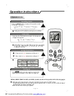
Страница 7: ...N FAN BUTTON ROOM TEMPERATURE SETTING BUTTONS SLEEP BUTTON ON OFF BUTTON SMART BUTTON MODE BUTTON TIMER SET CANCEL BUTTON Remote controller Indication symbols on LCD Note Each mode and relevant function will be further specified in following pages See page 9 Smart Mode for details PDF created with pdfFactory Pro trial version www pdffactory com ...

Страница 8: ...aim the remote controller to the signal receptor The remote controller will operate the air conditioner at a distance of up to 7m when pointing at signal receptor of indoor unit Choose Cooling Only Remote controller or Heat Pump Please refer to page 1 Preparation before use for details Back light Function optional Remote controller holder Signal receptor Remote controller Please refer to page 1 Pr...

Страница 9: ... of available set temperature HEATING COOLING DRY FAN unable to set room temperature Turning on SWING SMART TIMER SLEEP and SUPER operation modes will be specified in the following pages Press button when the appliance receives the signal the RUN indicator of the indoor unit lights up Changing modes during operation sometimes the unit does not response at once Wait 3 minutes Wait 3 minutes before ...

Страница 10: ...again when the louvers swing to a suitable angle as desired Horizontal airflow control with hands Turning the control rods of the horizontal adjustment louvers to change horizontal air flow as shown control rods of horizontal adjustment louvers Note The shape of the unit may look different from that of the air conditioner you have selected Do not turn the vertical adjustment louvers manually other...

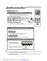
Страница 11: ...because of unsuitable air flow volume Uncomfortable because of unsuitable flow direction Press once to lower the set temp by 1 Press twice to lower the set temp by 2 Indoor fan speed alternates among High Medium and Low each time this button is pressed Press it once the vertical adjustment louver swings to change vertical airflow direction Press it again swings stops For horizontal airflow directi...

Страница 12: ...etting and indoor fan speed firstly then press the button and h flashes on LCD TIMER Point the remote control at the signal receptor of the indoor unit press the or button when h flashes Choose the timer you want then press the button TIMER A beep can be heard Timer indicator on the indoor unit lights up h stops flashing To cancel the set timer press the button again a beep can be heard and the ti...

Страница 13: ...above set temperature will not change Note Heating is NOT available for cooling only air conditioner SUPER mode is used to start or stop fast cooling SUPER mode can be set when the appliance is in operation or energized Fast cooling operates at high fan speed changing the set temperature automatically to 18 In SUPER mode you can set airflow direction or timer If you want to escape from SUPER mode ...

Страница 14: ...ater onto the indoor unit Reinstall and shut the front panel Reinstall and shut the front panel by pressing position b downward If the dirt is conspicuous wash it with a solution of detergent in lukewarm water After cleaning dry well in shade Clean the air filter every two weeks if the air conditioner operates in an extremely dusty environment Stop the appliance and remove the air filter 1 2 3 1 O...

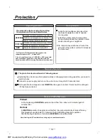
Страница 15: ...utlet of the outdoor unit lest it increases the noise level Features of HEATING mode Preheat Defrost At the beginning of operation the airflow from indoor unit is discharged 2 5 minutes later HEATING In operation the appliance will defrost de ice automatically to raise efficiency This procedure usually lasts 2 10 minutes During defrosting fans stop operation After defrosting completes it returns t...

Страница 16: ...nit to work The following cases may not always be a malfunction please check it before asking for service If strong interference from excessive static electricity discharge power supply voltage abnormality presents operation will be abnormal At this time disconnect from the power supply and connect back 2 3 seconds later Changing mode during operation 3 minutes will delay This odour may come from ...

Страница 17: ...er 50 mm should be over 50mm should be over 2000mm should be over 250mm Installation must be performed in accordance with the national wiring standards by authorized personnel only Above figure is only a simple presentation of the unit it may not match the external appearance of the unit you purchased 15 Installation instructions Installation diagram PDF created with pdfFactory Pro trial version w...

Страница 18: ...r air outlet Location for Installing Indoor Unit Where there is no obstacle near the air outlet and air can be easily blown to every corner Where piping and wall hole can be easily arranged Keep the required space from the unit to the ceiling and wall according to the installation diagram on previous page Where the air filter can be easily removed Keep the unit and remote controller 1m or more apa...

Страница 19: ...wall tidy and clean Drill a hole on the wall The hole should tilt a little downward toward outside Decide the position of hole for piping according to the location of mounting plate 2 Drill a Hole for Piping Keep the mounting plate horizontally with a horizontal ruler or dropping line Drill holes of 32mm in depth on the wall for fixing the plate Insert the plastic plugs to the hole fix the mountin...

Страница 20: ...back of the unit with a piping fixer Thermal insulation wrapped with vinyl type Small pipe Large pipe Thermal insulation tube Power connecting cord Drain hose prepared by user A Insert the pipe fixer to the slot B Press to hook the pipe fixer onto the base Base Base Base Piping fixer Piping fixer Hook here Insert here drain hose drain hose large pipe large pipe small pipe small pipe b Pre tighten ...

Страница 21: ...nside Access door Terminal inside Indoor unit Outdoor unit Installation instructions Caution 1 Never fail to have an individual power circuit specifically for the air conditioner As for the method of wiring refer to the circuit diagram posted on the inside of the access door 2 Comfirm that the cable thickness is as specified in the power source specification See the cable specification table below...

Страница 22: ...l No are the same as those of the indoor unit 24K Model Indoor unit For 24K model the power supply are connected from outdoor unit with a circuit breaker Outdoor unit Terminal Terminal 1 2 3 3 1 N 2 L Power connecting cord Blue Power supply Black Black Brown Brown 20 PDF created with pdfFactory Pro trial version www pdffactory com ...

Страница 23: ...he drain port and rubber washer to the chassis of the outdoor unit then connect a drain hose to the port as the right figure shown The air which contains moisture remaining in the refrigeration cycle may cause a malfunction on the compressor After connecting the indoor and outdoor units evacuate air and moisture from refrigerant cycle using a vacuum pump as shown below Refrigerant flow direction 2...

Страница 24: ... the supply cord is damaged it must be replaced by the manufacturer or its service agent or similarly qualified person in order to avoid a hazard In order to ensure the suitability of the equipment for connection the user should consult with the supply authority if necessary that the service current capacity at the interface point is sufficient for the equipment The power connection for the air co...

Страница 25: ...ay Noble Park 3174 03 9554 6245 Brisbane 116 Ipswich Rd Woollongabba 4102 07 3361 5858 Southport Shop 1 48 Ferry Rd Southport 4215 07 5591 3670 Adelaide 84A Richmond Rd Keswick 5053 08 8375 5710 Perth 45 Sarich Courl Osborne Park 6017 08 9445 5901 For Service in outer areas please contact your retailer for the address of the nearest Authorized NEC Service Centre NEC Australia Pty Ltd 244 Beecroft ...

Отзывы: