background image

P

LASMA

 M

ONITOR


 † 

43

Other Functions (OTHER SETTINGS)

Set [OSD MODE] to [PRO] on the configuration menu, then per-
form the following operations.

Preparation

Press the PROCEED button to display the main
menu.

4

1

Align the cursor with 

2

3

Move the cursor left and right with
the POSITION/CONTROL 


buttons.

COLOR SYSTEM
P-ON MODE
POWER MANAGER
SET ID NO
RGB3 ADJUST
CINEMA PULLDOWN
STD/CINEMA
ALL RESET

: AUTO

: OFF
: ALL
: 1
: ON
: STD

: LAST MEM

: AUTO

: OFF
: ALL
: 1
: ON
: STD

COLOR SYSTEM
P-ON MODE
POWER MANAGER
SET ID NO
RGB3 ADJUST
CINEMA PULLDOWN
STD/CINEMA
ALL RESET

: LAST MEM

Align the cursor with SET ID NO

Set the ID number with the

POSITION/CONTROL 


 buttons

Move the cursor up and down with
the POSITION/CONTROL 

▲▼

buttons.

Press the EXIT button 2 times

Press the EXIT button one time to return to the main menu.
One further press removes the menu.

* Aligning the cursor with [ALL RESET] and pressing the PRO-

CEED button will return all the settings of the other functions
to the default settings. (The ID number will become [ALL].)

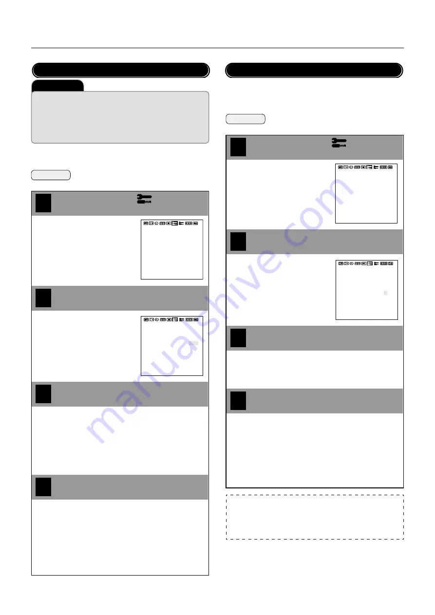
ID Number Setting (SET ID NO)

[ALL]

: ID number will not be set.

[001 to 256]: ID number will be set.

Adjust this setting when the RGB 3 image is not stable.
Set [OSD MODE] to [PRO] on the configuration menu, then per-
form the following operations.

Preparation

Press the PROCEED button to display the main
menu.

1

Align the cursor with 

2

3

Move the cursor left and right with
the POSITION/CONTROL 


buttons.

COLOR SYSTEM
P-ON MODE
POWER MANAGER
SET ID NO
RGB3 ADJUST
CINEMA PULLDOWN
STD/CINEMA
ALL RESET

: AUTO

: OFF
: ALL
: 1
: ON
: STD

: LAST MEM

: AUTO

: OFF
: ALL
: 1
: ON
: STD

COLOR SYSTEM
P-ON MODE
POWER MANAGER
SET ID NO
RGB3 ADJUST
CINEMA PULLDOWN
STD/CINEMA
ALL RESET

: LAST MEM

Align the cursor with RGB 3 ADJUST

Use the POSITION/CONTROL 


 buttons to set

the number that provides the best image

Move the cursor up and down with
the POSITION/CONTROL 

▲▼

buttons.

RGB 3 Adjustment (RGB 3 ADJUST)

4

Press the EXIT button 2 times

When the screen is not stable at [1] (the initial value), set the
adjustment to [2] or [3].

Press the EXIT button one time to return to the main menu.
One further press removes the menu.

* Aligning the cursor with [ALL RESET] and pressing the PRO-

CEED button will return all the settings of the other functions
to the default settings.

Note:

Making this adjustment will cause the display position to change. To com-
pensate, set [AUTO PICTURE] (of the [Auto Picture/Wide Screen Settings])
to [OFF] and then to [ON], or readjust the display position.

Important

When using more than one of these monitors, this function sets ID numbers
so that operation of the remote control does not cause multiple monitors to
operate at the same time.
(These ID numbers can also be used for control with RS-232C.)
The optional remote control is required to operate the plasma monitors for
each ID number independently. (These ID numbers also need to be assigned.)

Содержание PlasmaSync 42PD3

Страница 1: ...NEC Technologies PlasmaSync Plasma Monitor User s Manual ...

Страница 2: ...ctric shock 7 Do not attempt to service or repair the unit NEC is not liable for any bodily harm or damage caused if unqualified persons attempt service or open the back cover Refer all service to authorized NEC Service Centers RISK OF ELECTRIC SHOCK DO NOT OPEN CAUTION TO REDUCETHE RISK OF ELECTRIC SHOCK DO NOT REMOVE COVER NO USER SERVICEABLE PARTS INSIDE REFER SERVICING TO QUALI FIED SERVICE PE...

Страница 3: ...ld to reduce the likeli hood of perceptible phosphor burn or to diminish its perceptible effects if it occurs See pages 37 45 and 46 for instructions on how to use the Orbiter Low Brightness and Inverse RGB modes of AccuShield Lower the Brightness and Contrast levels as much as possible without impairing image readability Display an image with many colors and color gradations ie photographic or ph...

Страница 4: ...ir l appareil soi même NEC ne saura être tenu pour responsable pour toute blessure ou dommage causé par des personnes non qualifiées qui essayent de réparer ou d ouvrir le couvercle arrière Confier toute réparation à un centre de service agréé NEC RISQUE D ELECTROCUTION NE PAS OUVRIR MISE EN GARDE AFIN DE REDUIRE LES RISQUES D ELECTRO CUTION NE PAS DEPOSER LE COUVERCLE IL N Y A AUCUNE PIECE UTI LI...

Страница 5: ...x pages 37 45 et 46 pour plus de détails sur l utilisation des modes Orbiter Illumination Réduite et RVB In verse de l AccuShield Abaissez le niveau de l image contraste luminosité autant que possible sans faire perdre la lisibilité de l image Affichez une image avec de nombreuses couleurs et gradua tions de couleur par ex des images photographiques ou photo réalistes Créez un contenu d image avec...

Страница 6: ...s set up including ad justment of user controls These costs are the responsibility of the NECTECH dealer from whom the product was purchased 3 Payment of shipping charges HOW YOU CAN GET WARRANTY SERVICE 1 To obtain service on your product consult the dealer from whom you purchased the product 2 Whenever warranty service is required the original dated in voice or a copy must be presented as proof ...

Страница 7: ... POSITION and V POSITION 31 Direct Adjustment 31 Menu Adjustments 32 Input Selection INPUT SELECT 33 Standard Settings NORMAL 34 Information Screen DISPLAY MODE 35 Timer Settings PRESENT TIME 36 Time Settings 36 Timer Settings 36 4 Screen 9 Screen Multiple System Settings VIDEO WALL MENU 38 Menu Display Position Adjustment OSM LOCATION 39 Other Functions OTHER SETTINGS 40 Color System Settings COL...

Страница 8: ...g accessory For proper installation it is strongly recommended to use a trained NEC authorized service person Failure to follow correct mounting procedures could result in damage to the equipment or injury to the user or installer Product war ranty does not cover damage caused by improper installa tion Failure to follow these recommendations could re sult in voiding your warranty Ventilation Requi...

Страница 9: ...g a compo nent input the source is switched to the DVD HD input Can be used with Digital RGB input DVI standard compliant The signale plasma monitor provides four split screen feature Can be used with multiple screens 4 screen and 9 screen VIDEO WALL For 9 screen an optional distribution amplifier is needed for VIDEO WALL Power management function RGB3 input mode complies with DMPM Digital Monitor...

Страница 10: ...n Switches to the signal connected with the RGB input connec tor Toggle switches between RGB1 RGB2 DVD HD or RGB3 Functions as the button in the on screen menu OSM mode See also pages 22 and 25 u VIDEO button Switches to the signal connected with the VIDEO input con nector Functions as the button in the on screen menu OSM mode See also pages 22 and 25 i Remote control sensor Receives the signal fr...

Страница 11: ...IO IN 2 This is your audio input from your equipment such as a com puter VCR or DVD player u VIDEO VIDEO IN connector BNC Here is where you connect a composite video signal VIDEO OUT connector BNC You can use this connector to output the composite video signal from the VIDEO IN connector S VIDEO IN connector DIN 4 pin Here is where you con nect the S video Y C separate signal S VIDEO OUT connector...

Страница 12: ...r when there is an obstacle in the path Should this happen use the remote control in the wired operation Handling the remote control Remote Control POWER ON OFF button Switches the power on off See also page 21 If the POWER STANDBY lamp is not glowing then these controls will not work RGB 1 button Select the RGB1 input See also page 22 RGB 2 button Select the RGB 2 DVD HD input See also page 22 RG...

Страница 13: ...n the cover Align the batteries according to the and indications inside the case Replace the cover Connect external equipment See page 14 To protect the connected equipment turn off the main power before making connections Refer to your equipment user manual Connect the supplied power cable The power outlet socket should be installed as near to the equip ment as possible and should be easily acces...

Страница 14: ...ignal of input device VCR Audio signal of input device Personal computer DVD player Personal computer HD laser disk player Important Four Nine Multiple Screens System VIDEO WALL MENU Multiple System requires the optional Multiple Unit Contact your dealer for more information Use an optionally available BNC typed signal cable that is within 1 to 2 m 3 3 to 6 6 feet when one plasma monitor is connec...

Страница 15: ... HD IN connector BNC on the plasma monitor use the optional signal cable mini D sub 15 pin to BNC x 5 Select RGB for RGB 2 from the INPUT SELECT menu When connecting one or more Plasma monitors use the RGB 2 DVD HD OUT connector BNC The AUDIO IN 1 and 2 can be both used for audio input For connection select INPUT 1 or INPUT 2 from the SOUND menu Connections AUDIO OUT L R AUDIO IN 2 L MONO R VIDEO ...

Страница 16: ...parately mini D sub 15 pin to BNC x 5 Select RGB for RGB 2 from the INPUT SELECT menu When connecting one or more Plasma monitors use the RGB 2 DVD HD OUT connector BNC If you use with a Macintosh PowerBook set Mirroring to Off Refer to your Macintosh s owner s manual for more information about your computer s video output requirements and any special identification or configuring your monitor s i...

Страница 17: ...ignals conforming to DVI standards To maintain display quality use a cable with a quality prescribed by DVI standards that is within 2 meters 6 6 feet in length Attach the supplied small ferrite cores to the DVI signal cable See page 50 for attaching the ferrite cores The AUDIO IN 1 and 2 both RCA can be both used for audio input For connection select INPUT 1 or INPUT 2 from the SOUND menu AUDIO O...

Страница 18: ...ou will need a separately available BNC to RCA adapter to connect a VCR or laser disc player with an RCA pin jack to the BNC connector cable Video signals can be connected to either the VIDEO IN or the S VIDEO IN connector When making the connection use the input selection menu to set BNC or S VIDEO Video output will be from the OUT connector that has been set here When connecting one or more Plas...

Страница 19: ...parately available BNC connector cable You will need a separately available BNC to RCA adapter to connect a DVD player with an RCA pin jack to the BNC connector cable Some DVD players may have different connectors such as Y Cb Pb and Cr Pr Select DVD HD for RGB 2 from the INPUT SELECT menu When connecting one or more Plasma monitors use the RGB 2 DVD HD OUT connectors BNC The AUDIO IN 1 and 2 both...

Страница 20: ...fier Turn on the plasma monitor and the amplifier only after all hookups have been made Use an RCA cable to connect the AUDIO OUT connector RCA on the plasma monitor and the audio input on the amplifier Do not reverse the audio left and right jacks The AUDIO IN 1 and 2 both RCA can be both used for audio input For connection select INPUT 1 or INPUT 2 from the SOUND menu The AUDIO OUT jack outputs ...

Страница 21: ...o turn off the power standby mode Press the POWER button again The plasma monitor is in standby mode The POWER STANDBY light turns lit in orange POWER STANDBY Turning On or Off the Power with the Remote Control POWER STANDBY To turn on the plasma monitor Make sure that the POWER STANDBY light turns lit in orange standby Press the POWER ON button on the re mote control The plasma monitor is turned ...

Страница 22: ...is Active off Power state in DMPM of DVI standard An image will be displayed in 4 seconds after TMDS signal is returned Important Notes on the POWER STANDBY light on the plasma monitor When the indicator light flashes at a time other than during timer setting it indicates a fault of the monitor Should this happen immediately switch off the main power of the moni tor disconnect the power plug from ...

Страница 23: ...nt Image contrast adjustment Image sharpness adjustment Adjustment of color saturation Tint adjustment 28 28 28 28 28 Main Menu Page 1 Items OSD MODE BASIC and PRO AUTO PICTURE Auto picture Wide screen settings AUTO PICTURE INPUT MODE RGB MODE WIDE MODE PICTURE ADJ FINE PICTURE Sets the automatic adjustment of the clock frequency clock phase This is set when switching of input signal discriminatio...

Страница 24: ...ut mode that will be in effect when power is switched on Sets the power management function Sets ID numbers for up to 256 units Set when the RGB 3 image is not stable Sets the cinema pulldown Makes the settings for the standard image and the cinema image Returns the settings of all other functions to the default values 40 40 41 43 43 44 44 43 LUM LIMIT ORBITTING INV WT PROG ORBIT GRAY LEVEL ALL RE...

Страница 25: ...een of the CONFIG MENU does not contain icons that indicate menu items however operation is the same as with other screens Operation of the Menu Screen Main menu Sub menu The main menu comprises 2 pages screens Place the cursor on icon or and use the POSITION CONTROL button to change the page Set OSD MODE to PRO on the configuration menu before performing other operations VOLUME BALANCE MUTE INPUT...

Страница 26: ...void unwanted control from other remote controls SYNC MODE AUTO Automatically detects separate sync signals green sync signal i e sync on green and composite sync signal GSYNC Automatically detects green sync signal i e sync on green CSYNC Automatically detects composite sync signal PLE LINK ON Sets a uniform screen brightness for each screen in a 4 screen multiple system OFF Sets the screen brigh...

Страница 27: ...ns Press the EXIT button 2 times Press the EXIT button one time to return to the main menu One further press removes the menu Adjustment Screen VOLUME Adjusts the volume BALANCE Adjusts the left and right volume balance MUTE Switches off the sound temporarily OFF There is sound ON Sound is switched off INPUT 1 Each press serves to advance the audio input of AUDIO IN 1 by one step INPUT 2 Each pres...

Страница 28: ... cursor up and down with the POSITION CONTROL buttons Press the EXIT button 2 times Press the EXIT button one time to return to the main menu One further press removes the menu Adjustment Screen BRIGHTNESS Adjusts the brightness of the screen CONTRAST Adjusts the contrast of the image SHARPNESS Adjusts the sharpness of the image COLOR Adjusts the color saturation TINT Adjusts the tint These adjust...

Страница 29: ...ets the mode i e moving picture still picture mode to suit the input signal PICTURE ADJ Adjusts the clock frequency FINE PICTURE Adjusts the clock phase Press the EXIT button one time to return to the main menu One further press removes the menu Note AUTO PICTURE Adjustment of H POSITION and V POSITION is not available when AUTO PICTURE is set to ON at the time of RGB signal input When adjustment ...

Страница 30: ...ill occur though somewhat later even after making these settings and that burn in cannot be suppressed The moni tor should be used in FULL mode as much as possible 1 Perform gray level settings to narrow the differences in brightness be tween display and non display portions of the image See P 46 2 Weaken the image adjustment contrast and brightness See P 28 3 Perform the Long Life settings P 45 C...

Страница 31: ...justs the horizontal position and the vertical position of the screen A press of the button displays the adjustment screen Release your finger from the button after the adjustment is made The dis play will disappear about 3 seconds later and the adjustment de tails will be stored Move left Move right Move down Move up Vertical position adjustment POSITION CONTROL Horizontal position adjustment POS...

Страница 32: ...ress removes the menu Vertical position adjustment Adjusts the vertical position and height of the screen Preparation Press the PROCEED button to display the main menu 4 1 Align the cursor with 2 3 Move the cursor left and right with the POSITION CONTROL buttons V HEIGHT is adjustable only in multiple mode V POSITION V HEIGHT V POSITION V HEIGHT Align the cursor with the desired item Adjust with t...

Страница 33: ...ion INPUT SELECT This performs RGB 2 input selection and sets the SCART jack and VIDEO connector Preparation Press the PROCEED button to display the main menu RGB 2 Selects the signal connected to the RGB 2 DVD HD IN con nector RGB Set at time of RGB signal input DVD HD Set at time of DVD HD signal input SCART OFF Set so that the SCART jack is not connected ON Set to connect the SCART jack The SCA...

Страница 34: ...ne time to return to the main menu One further press removes the menu ALL RASTER NORMAL Returns the horizontal vertical position adjust ment auto picture wide screen settings and menu position adjustment to the default settings ALL VISUAL NORMAL Returns the audio settings image adjustments and color temperature adjustment to the default settings ALL NORMAL Simultaneously returns the setting detail...

Страница 35: ...input signal A 3 Hz error exists for signals with a vertical frequency between 60 Hz and 70 Hz and a 5 Hz error exists for signals with a vertical frequency above 70 Hz Please regard the frequency indications of the information screen in terms of reference values only Information Screen When RGB input is selected SOURCE INFO RGB 1 RGB 2 RGB 3 DVD HD H FREQ Horizontal frequency kHz V FREQ Vertical ...

Страница 36: ...n the configuration menu then per form the following operations Preparation Press the PROCEED button to display the main menu 4 1 Align the cursor with 2 3 Move the cursor left and right with the POSITION CONTROL buttons PRESENT TIME DATE 2001 AUG 10 TIME 22 30 SET TIMER OFF PRESENT TIME DATE 2001 AUG 10 TIME 22 30 SET TIMER OFF PRESS PROCEED FOR PROGRAM MENU Align the cursor with TIMER Turn the T...

Страница 37: ...et will differ de pending on the setting of Input Selection Note Programs Settings can be used in up to 7 programs Program contents are deleted after exiting the program Monitor POWER STANDBY Indicator The POWER STANDBY indicator blinks orange at 3 second intervals dur ing the setting of the timer at the time of monitor standby MODE SELECT MENU MODE RP REPEAT PROGRAM MODE1 TIME1 MODE2 TIME2 VIDEO ...

Страница 38: ... POSITION CONTROL buttons to set the number of screens Move the cursor up and down with the POSITION CONTROL buttons Align the cursor with POSITION Move the cursor up and down with the POSITION CONTROL buttons 1 1 screen There is no POSITION setting 4 4 screens 9 9 screens 8 6 7 4 screens 9 screens VIDEO WALL MENU 1 SCREEN DIVIDER 4 2 POSITION NO 4 3 DISP MODE SPLIT VIDEO WALL MENU 1 SCREEN DIVIDE...

Страница 39: ...in menu One further press removes the menu OSM H POS Adjusts the horizontal position of the menu display OSM V POS Adjusts the vertical position of the menu display OSM ANGLE Sets the menu display format to landscape HOR portrait VER OSM DISPLAY TIME Sets the menu display time 3 Align the cursor with OSM DISPLAY TIME 5 Move the cursor up and down with the POSITION CONTROL buttons OSM H POS OSM V P...

Страница 40: ...CAM Standard system for mainly France and Russia 4 43 NTSC System mainly used in VTRs in PAL SECAM regions Preparation Press the PROCEED button to display the main menu 1 2 3 Move the cursor left and right with the POSITION CONTROL buttons COLOR SYSTEM P ON MODE POWER MANAGER SET ID NO RGB3 ADJUST CINEMA PULLDOWN STD CINEMA ALL RESET AUTO OFF ALL 1 ON STD LAST MEM AUTO OFF ALL 1 ON STD COLOR SYSTE...

Страница 41: ... further press removes the menu Aligning the cursor with ALL RESET and pressing the PRO CEED button will return all the settings of the other functions to the default settings This sets the functions that serve to automatically reduce power consumption Set OSD MODE to PRO on the configuration menu then per form the following operations Power Management Settings POWER MANAGER Align the cursor with ...

Страница 42: ...State Off State POWER STANDBY Indicator Green Yellow Orange Orange Power Management Operation Status Not operating Operating Operating Operating Recovery Method Not required since the personal computer is nor mally being used at this time Press a keyboard key or move the mouse The screen will be displayed immediately Press a keyboard key or move the mouse The screen will be displayed however it wi...

Страница 43: ...ign the cursor with 2 3 Move the cursor left and right with the POSITION CONTROL buttons COLOR SYSTEM P ON MODE POWER MANAGER SET ID NO RGB3 ADJUST CINEMA PULLDOWN STD CINEMA ALL RESET AUTO OFF ALL 1 ON STD LAST MEM AUTO OFF ALL 1 ON STD COLOR SYSTEM P ON MODE POWER MANAGER SET ID NO RGB3 ADJUST CINEMA PULLDOWN STD CINEMA ALL RESET LAST MEM Align the cursor with RGB 3 ADJUST Use the POSITION CONTR...

Страница 44: ...D LAST MEM AUTO OFF ALL 1 ON STD COLOR SYSTEM P ON MODE POWER MANAGER SET ID NO RGB3 ADJUST CINEMA PULLDOWN STD CINEMA ALL RESET LAST MEM Note What is CINEMA PULLDOWN This is a mode to output DVD video information in a progressive signal format CINEMA PULLDOWN ON Normally set to ON This setting detects whether a DVD source was based on film or video When it was based on film it will be progres siv...

Страница 45: ...s in the horizontal direction V LINE Moves from 1 to 20 dots in the vertical direction TIME A 1 to 5 minute interval between movements Long Life Settings LONG LIFE MODE Preparation Press the PROCEED button to display the main menu 1 Align the cursor with 2 Move the cursor left and right with the POSITION CONTROL buttons LUM LIMIT ORBITTING INV WT PROG ORBIT GRAY LEVEL ALL RESET OFF OFF OFF 3 LONG ...

Страница 46: ...he brightness of non image portions that appear at top bottom left or right of the screen Set OSD MODE to PRO on the configuration menu then perform the following operations Gray level settings cannot be made in 4 screen or 9 screen systems Gray Level Settings GRAY LEVEL Important Gray Level Settings The gray level can be set to suit the level of gray brightness desired by the user There are marke...

Страница 47: ...with USER 1 to 4 then press the PROCEED button 4 5 Move the cursor left and right with the POSITION CONTROL buttons Each button press changes the setting by one step USER1 COLOR TEMP HIGH LOW PRESS PROCEED FOR GAIN BIAS SETTING R GAIN WHITE LEVEL G GAIN WHITE LEVEL B GAIN WHITE LEVEL R BIAS BLACK LEVEL G BIAS BLACK LEVEL B BIAS BLACK LEVEL Select the setting item with the POSITION CONTROL buttons ...

Страница 48: ...ime Release the tab Mounting of the Remote Control Holder A remote control holder can be mounted which will allow the remote control to be stored away when it isn t being used 1 2 Insert the top portion of the remote control holder into the up per side mounting holes at the left of the monitor terminal sec tion Insert the bottom portion of the remote control holder into the lower side mounting hol...

Страница 49: ...e bottom portion of the remote control holder Insert the upper portion of the remote control into the upper por tion of the remote control holder Insert until an engagement click is heard 1 2 Lift the upper portion of the remote control Disengage the lower part of the remote control from the remote control holder POWEROFF RGB 1 POWERON RGB 3 RGB 2 DVD HD VIDEO EXIT PROCEED POS ITIO N CONTROL RP 10...

Страница 50: ...VI signal cable Power cable DVI signal cable Ferrite core Large To power outlet To AC IN connector of monitor Ferrite core Small Ferrite core Small To equipment with a digital interface Cable tie Cable tie To the RGB 3 connector of this monitor Power cable DVI signal cable 1 2 Open the ferrite cores and clamp them on the DVI signal cable 3 Close the ferrite cores Fix the ferrite cores in place wit...

Страница 51: ...guration and Functions of External Control Connector Mini D Sub 9 Pin Application These specifications are applicable to NEC plasma monitors including 42 and 50 inch types and communications control from external equipment Connections Connections should be made as described below 1 Display side connector EXTERNAL CONTROL connector 2 External equipment side connector Serial port RS 232C connector S...

Страница 52: ...0 5 seconds until command processing is completed When command processing is completed an ACK2 for which bit 3 of Command 1 has been set to 1 at the end of command processing is returned every 0 5 seconds until command pro cessing is completed Bit 1 of Command 1 is set to 0 when the UA2 setting is FFH it is possible to simultaneously operate all sets connected in cascade and as a result ACK is not...

Страница 53: ...3H 44 SOUND INPUT Select CFH 05H 02H 45 VOLUME Gain Data Request 0FH 46H 00H 46 SOUND INPUT SELECT Request 0FH 60H 00H 47 CONFIG MENU Select CFH 06H 01H 48 TIMER PROGRAM Setting CFH 08H 0CH 49 MULTI DISP MODE Select CFH 07H 02H 50 MULTI DISP MODE Request 0FH 61H 00H 51 PRESENT TIME Setting CFH 09H 0AH 01 Connect Request Function The external control equipment requests a communications connec tion ...

Страница 54: ...Gain Flag 01H DATA01 RED Gain Flag 01H 08 GREEN Gain Data Function The external control equipment changes the GREEN gain data of the display This com mand will be received only when COLOR TEMP is set for USER 1 4 Transmission Data CFH UA1 UA2 11H 04H DATA00 DATA03 CKS DATA00 USER PICTURE Gain Flag 01H DATA01 GREEN Gain Flag 02H DATA02 GREEN Gain E0H 32 FFH 1 00H 0 20H 32 DATA03 GREEN Bias E0H 32 F...

Страница 55: ... UA2 16H 02H DATA00 DATA01 CKS DATA00 USER PICTURE Gain Flag 01H DATA01 SHARPNESS Gain Flag 06H 14 CONTRAST Gain Data Function The external control equipment changes the CONTRAST gain data of the display Transmission Data CFH UA1 UA2 17H 03H DATA00 DATA02 CKS DATA00 USER PICTURE Gain Flag 01H DATA01 CONTRAST Gain Flag 07H DATA02 CONTRAST Gain 00H 0 3FH 63 ACK 6FH UA1 UA2 17H 02H DATA00 DATA01 CKS ...

Страница 56: ...02H 18 PHASE Gain Data Function The external control equipment changes the clock phase of the display This command will be received only when AUTO PICTURE is OFF Transmission Data CFH UA1 UA2 1BH 03H DATA00 DATA01 DATA02 CKS DATA00 USER POSITION Gain Flag 03H DATA01 PHASE Gain Flag 03H DATA02 PHASE Gain 00H 0 1FH 31 ACK 6FH UA1 UA2 1BH 02H DATA00 DATA01 CKS DATA00 USER POSITION Gain Flag 03H DATA0...

Страница 57: ...C4 43 03H PAL 04H SECAM 96H AUTO ACK 6FH UA1 UA2 5CH 01H DATA00 CKS DATA00 01H NTSC3 58 02H NTSC4 43 03H PAL 04H SECAM 96H AUTO 28 INPUT MODE Request Function The display returns the current status for input mode requests of the external control equip ment Transmission Data 0FH UA1 UA2 41H 00H CKS ACK 6FH UA1 UA2 41H 01H DATA00 CKS DATA00 Input Select 01H Video 02H RGB1 03H RGB2 04H RGB3 05H HD DV...

Страница 58: ...The display returns the current status for screen adjustment information requests of the exter nal control equipment Transmission Data 0FH UA1 UA2 47H 00H CKS ACK 6FH UA1 UA2 47H 08H DATA00 DATA07 CKS DATA00 V POSITION Gain C0H 64 FFH 1 00H 0 40H 64 DATA01 H POSITION Gain C0H 64 FFH 1 00H 0 40H 64 DATA02 PHASE Gain 00H 0 1FH 31 DATA03 CLOCK Gain C0H 32 FFH 1 00H 0 20H 32 DATA04 00H fixed DATA05 00...

Страница 59: ...rocessor version decimal point and first right digit Microprocessor version first digit Seconds 1 s digit Seconds 10 s digit Minutes 1 s digit Minutes 10 s digit Hours 1 s digit Hours 10 s digit Day 1 s digit Day 10 s digit Month 1 s digit Month 10 s digit Year 1 s digit Year 10 s digit Appendix 35 SIGNAL Inform Function The display informs the external control equip ment of the input signal infor...

Страница 60: ...on The external control equipment switches on PICTURE Mute of the display Transmission Data 8FH UA1 UA2 3CH 00H CKS ACK 2FH UA1 UA2 3CH 00H CKS 39 PICTURE Mute Off Function The external control equipment switches off PICTURE Mute of the display Transmission Data 8FH UA1 UA2 3DH 00H CKS ACK 2FH UA1 UA2 3DH 00H CKS Appendix 40 MULTI MODE Select Function The master monitor changes MULTI MODE of the s...

Страница 61: ...he setting of bits 0 and 1 fixed as follows bit 0 1 and bit 1 1 ACK should be ignored in the case of a cas cade connection 43 VOLUME Gain Data Function The master monitor changes the volume gain data of the slave Transmission data CFH UA1 UA2 21H 03H DATA00 02 CKS DATA00 VOLUME Gain 00H 0 18H 24 DATA01 BALANCE Gain E8H 24 00H 0 18H 24 DATA02 MUTE 00H OFF 01H ON ACK 6FH UA1 UA2 21H 03H DATA00 02 CK...

Страница 62: ...6 OFF Time MIN 00H 09H 00 09 10H 19H 10 19 20H 29H 20 29 30H 39H 30 39 40H 49H 40 49 50H 59H 50 59 FFH No setting DATA07 Mode 00H VIDEO 01H RGB1 02H RGB2 HD SCART 03H RGB3 04H INV 05H WT 06H RP 07H RI FFH No setting DATA08 Repeat Program MODE1 00H VIDEO 01H RGB1 02H RGB2 HD SCART 03H RGB3 04H INV 05H WT FFH No setting DATA09 Repeat Program TIME1 00H 1 min 01H 2 min 02H 3 min 03H 4 min 04H 5 min 05...

Страница 63: ... two digits of year 00H 09H 00 09 10H 19H 10 19 20H 29H 20 29 30H 39H 30 39 40H 49H 40 49 50H 59H 50 59 60H 69H 60 69 70H 79H 70 79 80H 80H 80 89 90H 99H 90 99 DATA02 Month 01H 09H 1 9 10H 12H 10 12 DATA03 Day 01H 09H 1 9 10H 19H 10 19 20H 29H 20 29 30H 30H 30 31 DATA04 Hour 00H 09H 00 09 10H 19H 10 19 20H 23H 20 23 DATA05 Minute 00H 09H 00 09 10H 19H 10 19 20H 29H 20 29 30H 39H 30 39 40H 49H 40 4...

Страница 64: ...connection 13 No connection 14 5V Power 15 Ground 16 Hot Plug Detect 17 T M D S Data 0 18 T M D S Data 0 19 T M D S Data 0 Shield 20 No connection 21 No connection 22 T M D S Clock Shield 23 T M D S Clock 24 T M D S Clock 25 No connection 26 No connection 27 No connection 28 No connection 29 No connection 1 2 1 3 4 5 6 7 8 12 11 13 14 15 16 9 10 22 21 23 24 17 18 19 20 RGB3 Pin Configuration and S...

Страница 65: ...ty Ver Hor Ver Hor Resolution horizontal frequency vertical frequency Presence absence of sync Signal Identification For Raster Preset Appendix 1 Convert to 640 dots x 480 lines and display 2 These signals cannot be displayed in the RGB3 input mode 3 The picture will be shaky when the moving images of video games etc are input In this case set the refresh rate to 60 kHz or less 4 Only when using a...

Страница 66: ...Composite video signal Sync negative VIDEO IN THROUGH OUT Y 1 0Vp p 75 Ohms unbalanced Sync negative S VIDEO IN THROUGH OUT C 0 28Vp p 75 Ohms unbalanced Color burst level Audio Input Output Terminals AUDIO IN Stereo RCA X 2 AUDIO OUT Stereo RCA X 1 External Control mini D SUB 9 pin IN THROUGH OUT IN THROUGH OUT RS 232C Control Synchronization Range Horizontal 15 5 to 68 7 KHz automatic step scan ...

Страница 67: ...nto a power out let Set an ID number with the ID SELECT button or set the ID number to ALL Replace both batteries with new ones Point the remote control at the monitor s remote control sensor when pressing buttons or remove the obstacle Eliminate the light by closing curtains pointing the light in a different direction etc Use the remote control within 30º left and right of center at a diatance of...

Страница 68: ...rly hot move monitor to a cooler location and wait for the monitor to cool for 60 minutes If the problem persists contact your NEC dealer for service Symptom Checks Remedy Picture is unstable POWER STANDBY indicator is lighted in orange or yellow POWER STANDBY indicator is blinking in green Is the computer s resolution setting appropri ate Horizontal and or vertical sync signal is not present when...

Страница 69: ...PLASMA MONITOR 69 Cabinet dimensions Appendix 39 3 998 23 4 595 17 432 1 4 35 8 1 4 35 8 19 85 504 08 4 5 114 4 4 112 PlasmaSync 42PD3 Model PX 42VP3A Unit inch mm ...

Страница 70: ...NEC Technologies Inc 1250 N Arlington Heights Road Suite 500 Itasca Illinois 60143 1248 Printed in Japan 7S800461 ...

Отзывы: