Controls of
10
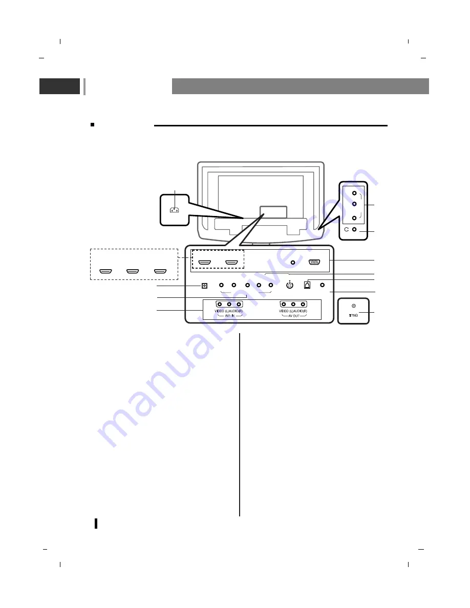
Back panel
1.
POWER CORD SOCKET
This set operates on an AC power. The volt-
age is indicated on the Specifications page.
Never attempt to operate the set on DC
power.
2.
HDMI1 IN (DVI) / HDMI2 IN (DVI) / RGB IN /
AUDIO IN SOCKETS
Connect the set output socket of the PER-
SONAL COMPUTER to this socket.
3.
DIGITAL AUDIO (OPTICAL) OUT
Connect digital audio from various types of
equipment.
Note
: In standby mode, these ports will not
work.
4.
COMPONENT IN (480i / 576i / 480p / 576p /
720p / 1080i) SOCKETS
5.
AUDIO/VIDEO IN SOCKET
Connect the audio/video out sockets of the
VCR to
AV
sockets of the set.
AUDIO/VIDEO OUT SOCKET
Connect a second TV or monitor.
AV OUT of DTV will only giving AUDIO OUTPUT.
This function works in the following mode :
TV, AV1, AV2, S-Video mode.
6.
S-VIDEO IN
Connect video out from an S-Video VCR to
the S-VIDEO input.
Connect the S-Video sound input socket of
the VCR to component sound sockets of the
set.
7.
RS-232 PORT
Connect to the RS-232 port on a PC.
8.
SERVICE ONLY SOCKET
9.
HEADPHONE SOCKET
Connect the headphone plug to this socket.
10. AERIAL SOCKET
- Shown is a simplified representation of the set.
- Here shown may be somewhat different from your set.
AC IN
(R)
(L)
VIDEO
AUDIO
AV
2
IN
Air
AUDIO IN
(RGB/DVI)
SERVICE
RGB IN
(PC/DTV)
DIGITAL AUDIO
(OPTICAL) OUT
HDMI1 IN (DVI)
HDMI2 IN (DVI)
Y
Pb
Pr
COMPONENT IN
(L) AUDIO (R)
S-VIDEO IN
RS-232
1
3
4
6
5
9
2
8
7
10
5
HDMI1 IN (DVI)
HDMI2 IN (DVI)
HDMI3 IN (DVI)
* NLT-40HDB3 model only
Содержание NLT-32HDB3
Страница 55: ...Note 55 ...
Страница 56: ...P No MAN07GDP064 v1 GPN07MA016E ...


