background image


21 

本装置上面側
のフック

本装置底面側
のフック

サイドカバーの裏側

筐体ロック
プレート


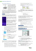
5. Move the front bezel toward upside to disengage three hooks 
    from the holes on bottom of the chassis, then remove the   

front bezel from chassis. 


6. Make sure that three kinds of filters are mounted on dust-proof bezel. See the figure below. 


7. Install the dust-proof front bezel in reverse order of   

removal procedure of front bezel. Insert the three tabs 
at bottom of dust-proof front bezel into holes at front   
of the server chassis (

in the figure), push the upper   

side of front bezel toward the server chassis   
(

in the figure), then lock the bezel with release tabs   

(

in the figure). 


8. Move the side cover toward the front of the server in the reverse order of installation procedure,   

then close the side cover (

in the figure).


●Make sure that hooks at both the top and bottom of the   
side cover are securely inserted in the holes on the server   
frame. Also make sure that the hooks at the front of the   
side cover are engaged with the server frame when sliding   
the side cover forward to attach. If they are not engaged 
with the frame, the side cover cannot be secured in place. 


Door filter case 

Bezel filter case 

Device filter frame 

Dust-proof filter (Blue) 

Dust-proof filter (Red) 
 

① 

① 

① 

Hooks at the top of the server


Insertion holes for the hooks


The hooks at the front of the server 

Plate for the chassis 
lock 
 

Hooks at the bottom of the server 


Rear view of side cover   

Insertion holes for the hooks 

Frame of the server 

③ 

③ 

③ 

② 
 

④ 

Slide  the  side  cover  to  the  direction 
shown by an arrow, and close it. 
 

Содержание N8146-36

Страница 1: ...1 N8146 36...

Страница 2: ...2 OFF...

Страница 3: ...3 1 Express5800 GT110e S 2 1 1 2 1 1 3 1 1 4 1 1 5 1 6 1 5 7 1 2 8 1 3 9 1 4 10 1 6 11 1 1 12 2 13 1 1 14 1 3 5 15 1 3 5 16 GT110e S 1 17 GT110e S 1 18 A 1 19 B 1 20 1...

Страница 4: ...4 2 5 USB 3 5 Express5800 GT110e S Express5800 GT110e S...

Страница 5: ...5 3 5 1 1 2 3 2 4 5 6 1 2 4 5 6...

Страница 6: ...6 3 GT110e S 93 0 mm X 411 5 mm X 363 0 mm 190 0 mm X 421 5 mm X 386 5 mm 1 2 3 4 3...

Страница 7: ...7 5 3 6 3 7 3 8...

Страница 8: ...8 9 A 10 B 10 1 10 2 3 10 3 3...

Страница 9: ...9 10 4 B 10 5 10 6 FAN B 10 7 8 FAN...

Страница 10: ...10 1 A B 2 3 3 A B 11 12 GT110e S GT110e S...

Страница 11: ...11 4 6 1 N8147 22 1 6 3 2 2 1 3 5 2 2 3 5 2 3 2 1 3 5...

Страница 12: ...12 3 3 1 2 5 3 2 3 3 3 4 4 4 1 4 2 4 3 2 5...

Страница 13: ...13 4 4 2 5 5 1 5 2...

Страница 14: ...14 5 3 5 4 6 3 1 2 3 4 5 4 856 129511 004 00 1...

Страница 15: ...danger These terms are defined as follows Precautions and notices against hazards are presented with one of the following two symbols The individual symbols are defined as follows Attentions Prohibit...

Страница 16: ...changes in temperature Place where vibration or impact may be generated Places with corrosive gas sulfur dioxide hydrogen sulfide nitrogen dioxide chlorine ammonia ozone etc in presence Places where t...

Страница 17: ...of vent holes cover 1 6 Vent holes cover filter frame 1 Installed on Item No 5 7 Dust proof filter Blue 1 Installed on Item No 2 8 Dust proof filter Black 1 Installed on Item No 3 9 Dust proof filter...

Страница 18: ...18 Cover for optical disk drive Cover for 2 5 inch hard disk drive bay Cover for USB ports Cover for 3 5 inch device bay Express5800 GT110e S Express5800 GT110e S...

Страница 19: ...ylinder lock 4 Insert your finger into a hole on accent cover and raise it up toward you to remove the accent cover Dispose of the removed accent cover 5 Put a blindfold label so that its non adhesive...

Страница 20: ...ncluded 1 Power off the server and disconnect the power cord 2 Pull the vent holes cover at the top of the server in the direction shown by an arrow in the figure and remove the vent holes cover 3 Lay...

Страница 21: ...he reverse order of installation procedure then close the side cover in the figure Make sure that hooks at both the top and bottom of the side cover are securely inserted in the holes on the server fr...

Страница 22: ...ction shown by an arrow and then remove it 10 2 Remove the side cover according to Step 3 10 3 Remove the screw shown in the figure below Secure the exhaust air filter A with a screw removed from the...

Страница 23: ...on the lower fan unit aligns with the center of hole on exhaust air filter B 10 7 Close the side cover according to Step 8 When using the server in vertical installation Remove the stabilizers from t...

Страница 24: ...to Section 3 Installing Removing the Bezel to the Server 11 Make sure that a filter is mounted on the provided dust proof vent holes cover insert the four claws into the grooves on top of the server w...

Страница 25: ...er from the chassis according to Section 3 Installing Removing the Bezel to the Server on page 6 2 Replacement of dust proof filter red 2 1 Open the cover of 3 5 inch device bay remove device filter f...

Страница 26: ...er case in reverse order of removal procedure 4 Replacement of dust proof filter black 4 1 Pull out the bezel filter case from bottom of rear face of dust proof bezel 4 2 Remove the dust proof filter...

Страница 27: ...vent holes cover filter frame Then remove the filter from vent holes cover filter frame Be sure to keep the vent holes cover filter frame for reuse 5 2 Hold the filter so that its surface without net...

Страница 28: ...en permission of NEC Corporation 2 The contents of this User s Guide may be revised without prior notice 3 The contents of this User s Guide shall not be copied or altered without the prior written pe...

Отзывы: