background image

English-11

English

1. Determine the installation location

CAUTION:

Installing your LCD display must be done by a
qualified technician. Contact your dealer for
more information.

CAUTION:

MOVING OR INSTALLING THE LCD MONITOR
MUST BE DONE BY TWO OR MORE PEOPLE.
Failure to follow this caution may result in injury if
the LCD monitor falls.

CAUTION:

Do not mount or operate the display upside
down, face up, or face down.

CAUTION:

This LCD has a temperature sensor and cooling
fan. If the LCD becomes too hot, the cooling fan
will turn on automatically. If the LCD becomes
overheated while the cooling fan is running, a
“Caution” warning will appear. If the “Caution”
warning appears, discontinue use and allow the
unit to cool. Using the cooling fan will reduce the
likelihood of early circuit failure and may help
reduce image degradation and “Image
Persistance”.
If the LCD is used in an enclosed area or if the
LCD panel is covered with a protective screen,
please check the inside temperature of the
monitor by using the “HEAT STATUS” control in
the OSD (see page 23). If the temperature is
higher than the normal operating temperature,
please turn the cooling fan to ON within the
SCREEN SAVER menu within the OSD (see
page 23).

IMPORTANT:

Lay the protective sheet, which was wrapped
around the LCD monitor when it was
packaged, beneath the LCD monitor so as
not to scratch the panel.

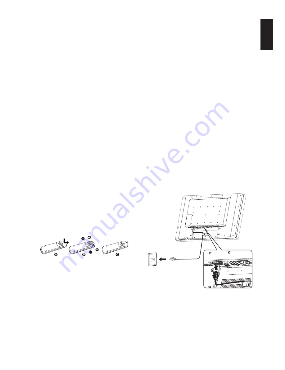
2. Install the remote control batteries

The remote control is powered by two 1.5V AAA batteries.
To install or replace batteries:

NEC recommends the following battery use:

Place “AAA” size batteries matching the (+) and (-) signs
on each battery to the (+) and (-) signs of the battery
compartment.

Do not mix battery brands.

Do not combine new and old batteries. This can shorten

battery life or cause liquid leakage of batteries.

Remove dead batteries immediately to prevent battery

acid from leaking into the battery compartment.

Do not touch exposed battery acid, it may injure skin.

NOTE:

If you do not intend to use the Remote Control for a
long period of time, remove the batteries.

3. Connect external equipment

(See pages


13-17)

To protect the external equipment; turn off the main
power before making connections.

Refer to your equipment user manual for further
information.

4. Connect the supplied power cord

The equipment should be installed close to an easily
accessible power outlet.

Fully insert the prongs into the power outlet socket.
A loose connection may cause image degradation.

NOTE:

Please refer to the “Safety Precautions and
Maintenance” section of this manual for proper
selection of AC power cord.

Setup

A. Press and slide to open the cover.

B. Align the batteries according to the (+) and (–)

indications inside the case.

C. Replace the cover.

CAUTION:

Incorrect usage of batteries can result in leaks
or bursting.

Содержание LCD4615 - MultiSync - 46" LCD Flat Panel...

Страница 1: ...User s Manual MultiSync LCD3215 MultiSync LCD4215 MultiSync LCD4615...

Страница 2: ...h 16 Connect the LCD Monitor to a DVD Player English 16 Connecting to a Stereo Amplifier English 17 Connect the LCD Monitor to a Stereo Amplifier English 17 Basic Operation English 18 Power ON and OFF...

Страница 3: ...ully in order to avoid any problems Declaration of the Manufacturer We hereby certify that the color monitor MultiSync LCD3215 L327HP MultiSync LCD4215 L427HQ MultiSync LCD4615 L467HZ are in complianc...

Страница 4: ...y one or more of the following measures Reorient or relocate the receiving antenna Increase the separation between the equipment and receiver Connect the equipment into an outlet on a circuit differen...

Страница 5: ...et reliability If using the cooling fan continuously it s recommended to wipe holes a minimum of once a month Immediately unplug your monitor from the wall outlet and refer servicing to qualified serv...

Страница 6: ...2 CD ROM Thumbscrew for stand x 2 LCD4215 and LCD4615 only CD ROM Screw for clamp M4 x 8 x 2 1 Type and number of power cords included will depend on the where the LCD monitor is to be shipped When mo...

Страница 7: ...t for detailed information Weight of LCD assembly MultiSync LCD3215 13 1 Kg MAX MultiSync LCD4215 21 6 Kg MAX MultiSync LCD4615 23 9 Kg MAX Installation Unit Mounting Bracket Screw 9 mm Thickness of B...

Страница 8: ...r Handle with care when mounting LCD monitor stand and avoid pinching your fingers VESA Mounting Interface 3 Ventilation Requirements When mounting in an enclosed space or recessed area leave adequate...

Страница 9: ...to turn main power ON OFF See also page 18 Control Key Lock Mode This control completely locks out access to all Control Key functions To activate the control key lock function press both and and hold...

Страница 10: ...SP4020 4620 for LCD4215 please use SP4020 4620 with large extension blocks included in speaker as if being mounted on LCD4620 LCD4215 is not mentioned in SP4020 4620 manual Kensington Lock LCD4215 an...

Страница 11: ...RGB for text based images CINEMA for movies MUTE button Turns on off mute function VOLUME UP DOWN button Increases or decreases audio output level Wireless Remote Control RGB1 RGB2 RGB3 DVD HD VIDEO S...

Страница 12: ...0 within a distance of about 3 5 m 10 ft Caution Important the remote control system may not function when direct sunlight or strong illumination strikes the remote control sensor of the LCD monitor o...

Страница 13: ...onitor when it was packaged beneath the LCD monitor so as not to scratch the panel 2 Install the remote control batteries The remote control is powered by two 1 5V AAA batteries To install or replace...

Страница 14: ...adjustments such as brightness or contrast when required 10 Recommended Adjustments To reduce the risk of the Image Persistence please adjust the following items based on the application being used PO...

Страница 15: ...each separate piece of equipment Wiring Diagram Personal computer BNC x 5 BNC x 3 RCA RCA RCA RCA To DVI output Mini D sub 15 pin To DVD Component video output DVD player To audio output BNC to RCA a...

Страница 16: ...BNC x 5 signal cable sold separately Select RGB3 from the INPUT button When connecting one or more LCD monitors use the RGB OUT connector mini D sub 15 pin RGB2 and RGB3 INPUT only AUDIO IN 1 2 and 3...

Страница 17: ...able Input TMDS signals conforming to DVI standards To maintain display quality use a cable that conforms to DVI standards AUDIO IN 1 2 and 3 can be used for audio input To select audio source AUDIO 1...

Страница 18: ...ee DVI MODE on page 24 AUDIO IN 1 2 and 3 can be used for audio input To select audio source AUDIO 1 AUDIO 2 or AUDIO 3 press the AUDIO INPUT button Connecting a DVD Player with component out Connecti...

Страница 19: ...lifier Do not reverse the audio left and right jacks The AUDIO IN is used for audio input The AUDIO OUT jack outputs sound from the selected Audio input Connecting to a Stereo Amplifier You can connec...

Страница 20: ...l turn green while powered on and will turn red while powered off NOTE The Main Power Switch must be in the ON position in order to power up the monitor using the remote control or the Power Button on...

Страница 21: ...n of the display Selecting a video source To view a video source Use the input button to set VIDEO S or VIDEO Use the COLOR SYSTEM menu to set AUTO PAL NTSC PAL60 4 43NTSC SECAM according to your vide...

Страница 22: ...ting to be adjusted Press EXIT button to exit Control Panel Press button to select Main menu and press Up Down button to enter Sub menu Press button to make setting to be adjusted OR EXIT button Then...

Страница 23: ...picture is standard and cannot be changed NOISE REDUCTION Adjusts the amount of noise reduction INPUT VIDEO S VIDEO only FILM MODE Selects Film mode function AUTO INPUT DVD HD VIDEO S VIDEO only This...

Страница 24: ...to power off after a length of time A time between 1 to 24 hours is available SCHEDULE Creates a working schedule for the monitor to use This OSD can t remove except EXIT See NOTE 1 on page 25 for fu...

Страница 25: ...ost signal Note When connecting DVI video card might not stop sending digital data even if image has disappeared In this case the monitor does not get to power management mode RGB Selecting ON the mon...

Страница 26: ...60 4 43NTSC SECAM AUTO Selects color system setting automatically base on input signal SCAN MODE Changes the display area of the image INPUT DVD HD VIDEO S VIDEO only OVER SCAN Set to display area abo...

Страница 27: ...st image of a previous image remains visible on the screen Unlike CRT monitors LCD monitors image persistence is not permanent but constant images being displayed for a long period of time should be a...

Страница 28: ...Contact your dealer for details In order to function the RS 232C OUT terminal can only be connected to another monitor of the same model Do not connect to other types of equipment To control monitor o...

Страница 29: ...lower power consumption level when on but not in use saving two thirds of your monitor energy costs reducing emissions and lowering the air conditioning costs of the workplace FullScan Capability Allo...

Страница 30: ...play card with respect to compatibility and recommended signal timings If your text is garbled change the video mode to non interlace and use 60Hz refresh rate Image of component signal is greenish Ch...

Страница 31: ...0 Vp p 75 ohm RCA NTSC PAL SECAM 4 43NTSC PAL60 Output Signal RGB 15pin Mini D sub Analog RGB 0 7 Vp p with 75 ohm terminated Separate HV sync TTL level Pos Neg VIDEO BNC Composite 1 0 Vp p with 75 o...

Страница 32: ...A NTSC PAL SECAM 4 43NTSC PAL60 Output Signal RGB 15pin Mini D sub Analog RGB 0 7 Vp p with 75 ohm terminated Separate HV sync TTL level Pos Neg VIDEO BNC Composite 1 0 Vp p with 75 ohm terminated AUD...

Страница 33: ...A NTSC PAL SECAM 4 43NTSC PAL60 Output Signal RGB 15pin Mini D sub Analog RGB 0 7 Vp p with 75 ohm terminated Separate HV sync TTL level Pos Neg VIDEO BNC Composite 1 0 Vp p with 75 ohm terminated AUD...

Страница 34: ...I D DVI 4 RS 232C input Pin No Name 1 connected to 7 8 2 RXD 3 TXD 4 connected to 6 5 GND 6 connected to 4 7 connected to 1 8 8 connected to 1 7 9 NC Pin Assignment of DVI connector 1 TX2 9 TX1 17 TX0...

Страница 35: ...http www necdisplay com in USA Energy Saving This monitor features an advanced energy saving capability When a VESA Display Power Management Signalling DPMS Standard signal is sent to the monitor the...

Отзывы: