background image

5. Make sure the appropriate BNC cable is used.  Should the 

graphics adapter require a connector other than the 15 pin 

mini D-sub male included with the monitor, please call NEC 

at (800) 820-1230. Connect cable to system.

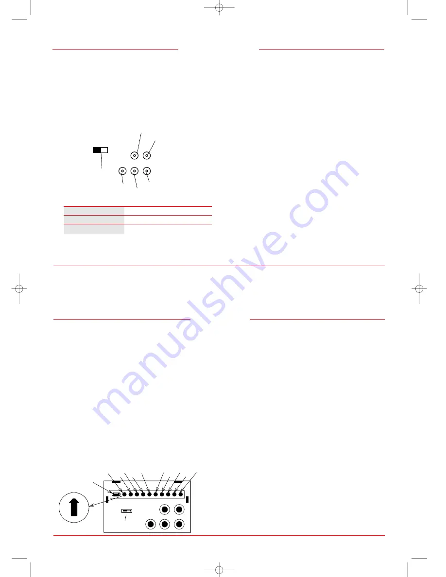
6. Connect BNC cables as follows according to the input video 

mode selected above.  (Note: incorrect cable connections 

may result in irregular operation, damage display quality/

components of LCD module, and/or shorten the 

module’s life.)

Input Video Mode H/CS

VS

R G/SYNC B

Separate Sync

O

O O

O

O

Composite Sync

O

X

O

O

O

Sync on Green

X

X

O

O

O

O - BNC connector is utilized; X - BNC connector is not utilized

Connect the red BNC cable to the BNC connector on the 

monitor labeled R.  The green BNC cable should be connec-

ted to the BNC connector on the monitor labeled G.  The 

blue BNC cable should be connected to the BNC connector 

on the monitor labeled B.  If you have a fourth BNC connec-

tor (Composite Sync), connect it to the BNC connector on the 

monitor labeled H/CS.  If you have a fifth BNC connector 

(Vertical Sync), connect it to the BNC connector on the moni-

tor labeled VS.  Please see Appendix 1 for pin assignments.

7. Connect one end of the power cable to the LCD1280 

monitor and the other end to the power outlet.

8. Turn on the monitor and the computer.

Note:  If the settings and connections were made properly, 

the LED on the front of the LCD1280 will show green.  

If the LED displays an amber color, the monitor is not receiv-

ing the appropriate input.  Please make certain that the 

above settings were made properly.  If the LED continues 

to display an amber color or the monitor is not displaying 

a stable image, please refer to the Troubleshooting section 

of this manual.

9. This completes the installation.

Front Controls:

Brightness:

slide type control adjusts the overall image

and background screen brightness.

LED Power Indicator Light:

indicates the monitor’s power

mode.  Each mode reduces the amount of power used

by the monitor:

Mode

Light

ON

green

Stand By & Suspend

amber

Power Switch, OFF

no light

Side Control:

Power Switch:

push type button located on right side of

monitor base turns the power on or off.  When the

power is on, the LED is lit.

Rear Controls:

SYNC Mode Select Switch:

allows selection between

Standard mode (OFF) and Sync on Green (ON) 

priority mode.

H-SEL Pixel Frequency Select Switch: 

selects the external

pixel clock source for WS timing 1 (107.5 MHz) or

WS timing 2 (107.352 MHz).

WS Clock Delay Adjust (H-C):

adjustment of WS pixel

clock delay rate.

Rough WS Horizontal Adjust (H-H1):

rough adjustment

for horizontal position of WS mode (16 dot increment

per operation).

Fine WS Horizontal Adjust (H-H2):

fine adjustment for

horizontal position of WS mode (1 dot increment per

operation).

Rough WS Vertical Adjust (H-V1):

rough adjustment for

vertical position of WS mode (16 line increment per

operation).

Fine WS Vertical Adjust (H-V2):

fine adjustment for 

vertical position of WS mode (1 line increment per

operation).

VGA Clock Delay Adjust (V-C):

adjustment of VGA pixel

clock delay rate.

Rough VGA Horizontal Adjust (V-H1):

rough adjustment

for horizontal position of VGA mode (32 pixel / 16

dot increment per operation).

Controls

6

7

Installation

H Sync/Composite Sync

V Sync

Sync Mode Select

Green / Sync on Green

Red

Blue

G/SYNC

B

H/CS

OFF

ON

SYNC

VS

R

C

E

A

8

6

4

SYNC

OFF

Sync Mode Select

H-SEL
Pixel Frequency
Select

H/CS

VS

G/SYNC

R

B

H-C

H-H1

H-H2

H-V1

V-C

V-H1

V-H2

V-V1

V-V2

H-V2

ON

2

0

Display Position / Clock Delay Adjust

LCD1280  10/29/99 9:25 AM  Page 6

Содержание LA-1331JSW

Страница 1: ...User s Manual Part No Printed in U S A NEC Technologies Inc 1255 N Michael Drive Wood Dale Illinois 60191 1094 13 True Color TFT LCD Monitor 13 True Color TFT LCD Monitor LCD1280 10 29 99 9 25 AM Page 1 ...

Страница 2: ...280 Specifications 3 Installation 5 Recommended Use 5 Connection to Graphics Cards using BNC cables 5 Controls 7 Front Controls 7 Side Control 7 Rear Controls 7 Troubleshooting Support 9 Troubleshooting Chart 9 Technical Support 10 BBS 10 FastFacts 10 Warranty 10 Appendix 1 13 Pin Assignment Table 13 Appendix 2 14 Signal Timings 14 Appendix 3 17 Signal Levels 17 References 18 Index 18 Information ...

Страница 3: ... for today s sophisticated Windows Macintosh Silicon Graphics Sun and other workstation applications In addition to offering support for VGA graphics mode 640 x 480 the LCD1280 supports WS high resolution mode 1280 x 1024 The LCD1280 automatically detects and changes between WS high resolution mode and VGA graphics mode The LCD1280 can display an infinite number of colors in its high resolution mo...

Страница 4: ...tness control are positioned within easy reach and the tilt base adjusts to each individual s preferred angle of vision The LCD1280 monitor s cabinet design and aesthetics look good from all angles Reduced Emissions Incorporating NEC s own Reduced Magnetic Field tech nology the LCD1280 has minimal field emissions and follows the strictest magnetic field alternating electric field and electro stati...

Страница 5: ...laying fixed patterns on the monitor for extremely long periods of time to avoid after image effects Connection to Graphics Cards using BNC cables The NEC LCD1280 color monitor complements a host of computing platforms However because the LCD1280 is a high resolution full color analog monitor it may require the use of a graphics card sometimes referred to as a video card video adapter or graphics ...

Страница 6: ...refer to the Troubleshooting section of this manual 9 This completes the installation Front Controls Brightness slide type control adjusts the overall image and background screen brightness LED Power Indicator Light indicates the monitor s power mode Each mode reduces the amount of power used by the monitor Mode Light ON green Stand By Suspend amber Power Switch OFF no light Side Control Power Swi...

Страница 7: ...llation section of this manual Image is unstable or swimming Signal cable should be completely attached to the computer is apparent Check the monitor and your video card with respect to compatability and recommended signal timings Please see FastFacts document 52301280 and Appendix 2 Check the SYNC Switch and H SEL Switch for their correct position LED on the monitor is not lit Power Switch should...

Страница 8: ... days Who is Protected This warranty may be enforced only by the first consumer purchaser and is not transferable What is Covered and What is not Covered Except as specified below this warranty covers all defects in material or workmanship in this Product The following are not covered by this warranty 1 Any Product which is not distributed in the U S A or Canada by NECTECH or which is not purchase...

Страница 9: ... in accordance with the terms of this limited warranty Consumers are cautioned that Product performance is affected by system configuration software the application customer data and operator control of the system among other factors While NEC TECHNOLOGIES INC Products are considered to be compatible with many systems the specific functional implementation by the customers of the Product may vary ...

Страница 10: ...548msec 35H Vertical front porch Tvf 0 108msec 7H 0 047msec 3H IMPORTANT The Jitter on Hsync output from video card should be less than 300 psec or you may see some jitter on the screen Appendix 2 Input Signal Timings VGA Mode The values of Front Back porch are for reference only Item Abbreviation Monitor Rating Pixel frequency fc 25 175MHz 50ppm 39 72nsec pixel Horizontal frequency fh 31 469KHz L...

Страница 11: ... Level Fig A3 1 Separate video wave forms Black Level White Level Video swing Setup Blank Level Sync Level Fig A3 2 Sync on Green video wave forms Black Level Hsync Video Ground Level VAIO Fig A3 3 Video input offset Horizontal H Video Th Thd Thp Thb Thf Fig A2 1 Horizontal Timing V Video Vertical Tvd Tv Tvp Tvb Tvf Fig A2 2 Vertical Timing V sync Th Thrf Thrf 2 0V 0 8V H sync H sync Fig A2 3 Sync...

Страница 12: ...2 Pin Assignments 13 Position Controls 7 Power Consumption 2 4 Power Supply 4 Reduced Footprint 1 Reduced Magnetic Field Technology 2 Remote Bulletin Board System BBS 10 Resolution 1 3 Separate Sync 6 13 Signal Levels 17 Signal Timings 14 15 Specifications 3 4 Sync on Green 6 13 SYNC Switch 5 7 Synchronization Range 3 Technical Support 10 Tilt Base 2 4 Timing Charts 14 15 Troubleshooting 9 VESA 2 ...

Отзывы: