background image

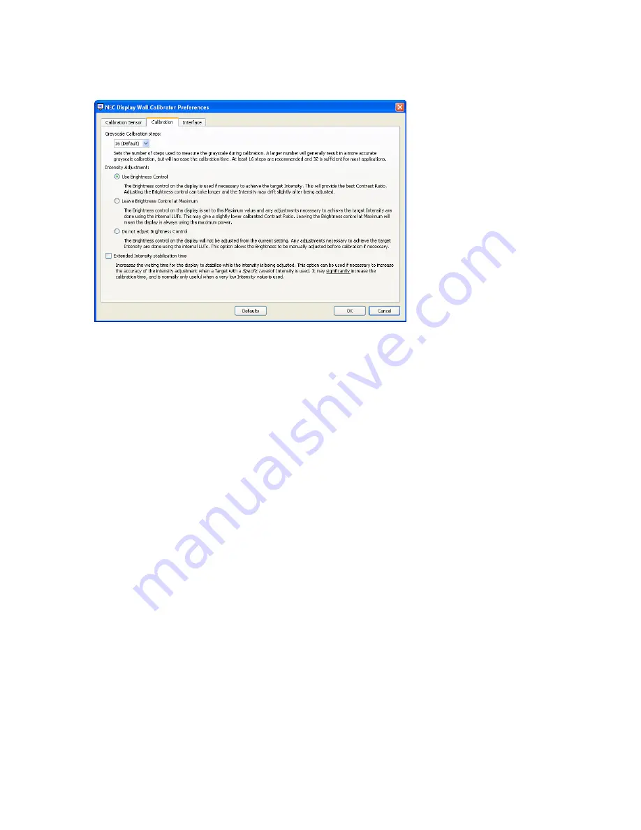
Calibration  and  Profile  Steps 

-  Selects  the  number  of  measurement  steps  to  take  when  calibrating  the 

display. A larger number of steps will generally result in a more accurate grayscale calibration, but will increase 

the calibration time. 16 steps is the recommended setting for most applications. 

Intensity Adjustment

  -  Sets  how  a  particular  Intensity  value  is  achieved  during  the  calibration  process  if 

necessary. 
Options are:

Use Brightness Control

 - The Brightness control on the display is used if necessary to achieve the 

target Intensity. This will provide the best possible Contrast Ratio and also lowest power consumption 

(assuming the target Intensity used results in the brightness control being reduced from maximum). 

Adjusting the Brightness control can increase the calibration time slightly, and the Intensity may drift 

slightly after being adjusted. Because the range of the Brightness control is limited, any additional 

adjustments necessary to achieve the target Intensity are done using the internal LUTs.

Leave Brightness Control at Maximum

 - The Brightness control on the display is set to the 

maximum value and any adjustments necessary to achieve the target Intensity are done using 

the internal LUTs.  This may give a slightly lower calibrated Contrast Ratio, and the display power 

consumption will always highest. The calibration time is fastest for this method.

Do not adjust Brightness Control

 - The Brightness control on the display will not be adjusted 

from the current setting. Any adjustments necessary to achieve the target Intensity are done using the 

internal LUTs if possible. This option allows the Brightness to be manually adjusted before calibration if 

necessary. Since the Brightness control is not adjusted, the Intensity can not be increased if necessary 

during calibration.

Extended luminance stabilization time

 - Increases the waiting time for the display to stabilize while the 

luminance is being adjusted by using the Brightness control. This option can be used if necessary to increase 

the accuracy of the luminance adjustment when a Target with a Specific Level of Intensity is being used. It may 

significantly increase the calibration time, and is normally only useful when a very low intensity value is used. 

Try selecting this option if the Intensity measured after calibration is significantly different than the Target value 

due to the display stabilizing during the calibration and profiling steps.


NEC Display Wall Calibrator - UsEr’s GUiDE  | 

Preferences dialog - Calibration tab

Содержание KT-X46UN

Страница 1: ...Version 1 0 00 User s Guide...

Страница 2: ...acintosh Mac and the Mac logo are trademarks of Apple Computer Inc registered in the U S and other countries Copyright 2009 NEC Display Solutions Ltd The content of this manual is furnished for inform...

Страница 3: ...OR FITNESS FOR A PARTICULAR PURPOSE SOME STATES DO NOT ALLOW THE EXCLUSION OF IMPLIED WARRANTIES OR THE LIMITATION OR EXCLUSION OF LIABILITY FOR INCIDENTAL OR CONSEQUENTIAL DAMAGES SO THE ABOVE EXCLUS...

Страница 4: ...LAN with daisy chained RS232 18 Multi IP LAN 19 Wireless multi IP LAN with daisy chained RS232 20 Configuring a Layout with the Layout Wizard 21 Calibration Times 25 Video Inputs 25 4 Dialogs Setting...

Страница 5: ...tion tab 43 Display Settings dialog Status tab 43 Summary window 44 Menus 45 File menu 45 Edit menu 45 View menu 45 Help menu 45 5 Quick Start to NEC Display Wall Calibrator 46 6 Frequently Asked Ques...

Страница 6: ...Always store the color sensor in the holder when not in use Never touch the measurement window in the color sensor Never disconnect the color sensor while the NEC Display Wall Calibrator software is...

Страница 7: ...One Monitor Eye One Pro X Rite ColorMunki Monaco OptixXR X Rite DTP 94 ColorVision Datacolor Spyder 2 Datacolor Spyder 3 USB At least one available USB port for Color Sensor An active USB extender ca...

Страница 8: ...of video signal to the displays in the video wall as test patterns are automatically generated within in each display Communications with each display from the host PC are performed via either RS232 o...

Страница 9: ...t highly accurate color can be achieved not only at 100 white but at all steps along the grayscale A variety of different Tone Response Curves can be applied also from something as simple as a small s...

Страница 10: ...the monitors to the color characteristics in the selected Target When calibrating a video wall careful consideration should be made as to how the displays will be calibrated so that they match as nece...

Страница 11: ...t each individual display can achieve while matching up the white points on each display Use this option if it is desired that all of the displays match in color but is not important if they match eac...

Страница 12: ...being used for does not need a specific White Point and the brightest possible display is required a White Point that will achieve the highest possible overall Intensity after calibrating can be autom...

Страница 13: ...bration process for a video wall when matching both the Intensity and White Point is outlined in the following steps Initialize Displays This step resets each display to the default color settings so...

Страница 14: ...nalogVideo Inputs Important Notice The display calibration process adjusts the digital portion of the video processing within the display For analog video signals such as VGA RGB HV and Option Analog...

Страница 15: ...ing on the calibration Target type being used it may be necessary to measure all of the displays in the video wall in order to determine the dimmest display The physical wiring connection order betwee...

Страница 16: ...The cable connections between displays does not need to follow the same ordering as the ID assignments In this example the daisy chain is connected in order 1 2 4 3 The following image shows how this...

Страница 17: ...aisy chain must have a unique MONITOR ID The following image shows how this layout looks in the Summary window when configured Notice that displays connected on COM1 can have the same IDs as those on...

Страница 18: ...ay Since communications to all of the displays is routed through the first display the software is configured to use the IP address of the first display for each display The first display will transla...

Страница 19: ...P address and MONITOR ID of each display The ID of each display does not need to be unique since the displays are not daisy chained however the ID set on the OSD must match that set in the software Th...

Страница 20: ...configured to so that Display 2 uses the IP address of Display 1 even though Display 2 is configured to use RS232 on the OSD Likewise the software is configured so that Display 4 uses the IP address...

Страница 21: ...iguration settings for individual displays can be made if necessary using the Connection panel In the following configuration example a 3x2 video wall that uses a LAN connection for communications to...

Страница 22: ...rest of the displays This display will also be the first one to be measured and calibrated when automatically performing these actions on all displays Next the order of remaining displays can be selec...

Страница 23: ...the video wall will use an RS232 daisy chain to communicate via the LAN connection on the first display Next the connection method for the remaining displays must be selected Two options are available...

Страница 24: ...It is possible to see the resulting connection configuration by opening the Summary window In this example all 6 displays have been assigned the same IP address in the software even though only the fi...

Страница 25: ...en the Measurement process can be skipped For example if it is known from a previous set of measurements that all of the displays can achieve an Intensity of at least 400 cd m2 at a particular White P...

Страница 26: ...f this window are shown below Calibration Target Shows the current Calibration Target settings Click Edit to open the Calibration Target Configuration dialog box used to modify Target settings Display...

Страница 27: ...rently selected display is highlighted by a rectangle The layout including the number of rows and columns in the video wall and order of the displays is configured by using the Layout Wizard An indivi...

Страница 28: ...e a match in both Intensity and White Point Use this option if you want all of the displays to match in both color and brightness All of the displays will only be as bright as the dimmest display Maxi...

Страница 29: ...amma value of 2 2 is popular for most applications DICOM Curve The response curve follows the DICOM Digital Imaging and Communications in Medicine specification This response curve is aimed at medical...

Страница 30: ...re perceptually uniform than a simple gamma value curve NTSC Video A curve based on the SMPTE 170M specification for NTSC that includes the offset transition and slope components SMPTE 240M A curve ba...

Страница 31: ...ordinates are automatically calculated and displayed for reference CIE xy chromaticity coordinates can be entered by selecting the CIE Coordinates radio button and entering the x and y values The corr...

Страница 32: ...hen it may be necessary to re detect it Note If the sensor was not attached when NEC Display Wall Calibrator was launched then it may be necessary to exit the NEC Display Wall Calibrator application a...

Страница 33: ...ve the target Intensity are done using the internal LUTs This may give a slightly lower calibrated Contrast Ratio and the display power consumption will always highest The calibration time is fastest...

Страница 34: ...Preferences dialog Interface tab 34 NEC Display Wall Calibrator USER S GUIDE Luminance Units Selects the units that luminance values are displayed in Options are Candelas cd m Foot Lamberts fL...

Страница 35: ...are measured There is no need to interact with the host PC while the displays are being measured with this option since the next display is selected automatically and the routine will wait until the c...

Страница 36: ...ted by clicking the Test button This will attempt to communicate with the display on the selected communications interface and Monitor ID Clicking the Update button will update the communications conn...

Страница 37: ...body radiator temperature of the measurement in Kelvin The uv Delta uv value indicates how far the measurement is from the blackbody radiator locus The Kelvin value is only meaningful for colors that...

Страница 38: ...ted White pattern is only available if the display has been calibrated and shows the adjusted white after calibration It is useful to visually evaluate the calibration accuracy Clicking Off will turn...

Страница 39: ...n Settings Will re configure displays with the settings from the last calibration This can be useful to switch between different calibrations by loading different projects and restoring the calibratio...

Страница 40: ...his gives an indication as to the accuracy of the calibration compared to the Target value as well as how far the display needed to be adjusted from the native state in order to achieve the Target Whi...

Страница 41: ...an be applied to either a single display or to all of the displays in the current project by selecting either Selected Display or All Displays Display Settings dialog Power tab The Clock tab is used t...

Страница 42: ...the video This operation should be performed whenever a new analog video signal is connected when a major change is made to the video wiring to the display or when a video amplifier or splitter is ad...

Страница 43: ...ed settings Select the video inputs to apply the calibrated settings to and click the Apply button Display Settings dialog Calibration tab The Status tab reports various aspects about the currently se...

Страница 44: ...y method is set to Specific Level and the calculated value is more than 5 lower than the Target then a yellow warning icon is shown to warn that the displays may not match in Intensity after calibrati...

Страница 45: ...shows the Connection panel Calibration Target Hides or shows the Calibration Target panel Colorimeter Hides or shows the Colorimeter panel Display Measurements Hides or shows the Display Measurements...

Страница 46: ...Layout and Connections Use the Layout Wizard from the Edit menu to specify the number of displays their layout calibration order and connection method If necessary modify the connection settings for...

Страница 47: ...ate All button on the Actions panel to start the calibration process You will be prompted to place the sensor on the screen of each display in turn The display to place the sensor on will flash altern...

Страница 48: ...ll Answer The time until the displays need to be re calibrated will depend on many factors such as the environment and duration they are used the age of the displays the calibration Target settings us...

Страница 49: ...other displays on the same chain have the same MONITOR ID Make sure that each display is connected via a NULL modem cable and that the correct IN our OUT socket on the display is used Make sure that n...

Страница 50: ...or if a major change was made to the video wiring to the display or a video amplifier or splitter was added to the video source Auto Setup can be accessed from the OSD on each display or by using the...

Страница 51: ...rMunki software is running and give the option of closing it automatically To use the ColorMunki software again after NEC Display Wall Calibrator has closed it you must run the colormunki exe applicat...

Страница 52: ...set the IP address of the display is not currently set to access the subnet that includes the display s defaults IP address it will be necessary to temporarily modify the network settings in order to...

Страница 53: ...wser It may take several refreshes before the display can be found Check if any firewall software or settings on the PC could be preventing access to the display s IP address Once the web page has app...

Страница 54: ...but is often referred to as just Candelas or Nits for sake of brevity CCFL Cold cathode fluorescent lamp used for the backlight on LCD display panels CIE The Commission Internationale d Eclairage Int...

Страница 55: ...colors that a device can produce DICOM Digital Imaging and Communications in Medicine Foot Lamberts fL A unit of luminance One foot Lambert is equal to 1 Candela per meter squared divided by 10 76 app...

Страница 56: ...s networked computers and devices that have a common designated IP address routing prefix TCP IP Transmission Control Protocol Internet Protocol Tone Response Curve A graph representing the relationsh...

Страница 57: ...Copyright 2009 NEC Display Solutions Ltd All rights reserved USA and Canada www necdisplay com Europe www nec display solutions com Asia Pacific www nec display com ap contact...

Отзывы: