background image

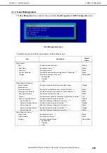
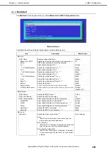
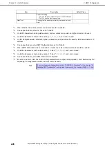
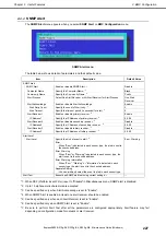
2. BMC Configuration 

Express5800/R310g-E4, R320g-E4, R320g-M4  Maintenance Guide (Windows) 

230

Chapter 3  Useful Features 

2.5 


BMC Initialization 

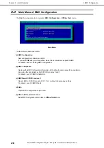
If you select 

BMC Initialization

 on 

Main

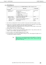
 menu, the confirmation message as show below appears.   

Only the CPU/IO module installed in the server appears on this menu. 


Confirmation message (BMC Initialization) 

<

ESC

> key:  Stops processing and returns to 

Main

 menu. 

<

Enter

> key:  Initializes BMC configuration settings and restores the default value except for some items.   

After initialization, it takes about 3 minutes to restart BMC. 


Note 

Do not shutdown the system, reboot the system, or perform any switch operation 
while BMC is being initialized (for approximately 3 minutes). 


2.6 


BMC Reset 

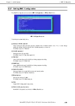
If you select 

BMC Reset : CPU/IO module X

 on 

Main

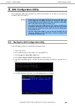
 menu, the confirmation message as show below appears. 

Only the CPU/IO module installed in the server appears on this menu. 


Confirmation message (BMC Reset) 

<

ESC

> key:  Stops processing and returns to Main menu. 

<

Enter

> key:  Resets BMC of CPU/IO module X (X = 0 or 1). It takes about 90 seconds to restart BMC. 


Note 

Do not shutdown the system, reboot the system, or perform any switch operation 
while BMC is being reset (for approximately 90 seconds). 


Содержание Express5800/R320g-M4

Страница 1: ...nd Upgrading the System Chapter 3 Useful Features Maintenance Guide Windows NEC Express Server Express5800 Series Express5800 R310g E4 Express5800 R320g E4 Express5800 R320g M4 EXP320T EXP320V 30 104...

Страница 2: ...em BIOS configurations and summary of EXPRESSBUILDER Chapter 4 Appendix Specifications Installation Guide Windows Chapter 1 Installing Operating System Installation of OS and drivers and precautions f...

Страница 3: ...4 Making Backup Copies 20 2 5 Cleaning 20 Cleaning the Express5800 ft series 21 2 5 1 Cleaning Tape Drive 21 2 5 2 Cleaning the Keyboard and Mouse 21 2 5 3 3 User Support 22 3 1 Maintenance Services 2...

Страница 4: ...Collecting User Mode Process Dump 77 7 5 Collecting Memory Dump 77 8 Troubleshooting 79 8 1 Problem of Powering on 80 8 2 Problem of EXPRESSBUILDER 81 8 3 Problem of Installing OS 82 8 4 Problem of St...

Страница 5: ...alling replacing optional devices 148 5 2 Available Optional Devices 149 5 3 2 5 inch Hard Disk Drive 150 5 3 1 Installing 2 5 inch Hard Disk Drive 151 5 3 2 Removing 2 5 inch Hard Disk Drive 153 5 3...

Страница 6: ...he SAS Configuration Utility 232 3 3 Physical Formatting of the Hard Disk Drive 232 4 Flash FDD 235 4 1 Notes on Using Flash FDD 235 4 1 1 Compensation for recorded data 235 4 1 2 Handling Flash FDD 2...

Страница 7: ...This symbol indicates the presence of a hazard if the instruction is ignored An image in the symbol illustrates the hazard type Example Prohibited Action This symbol indicates prohibited actions An im...

Страница 8: ...ther serious malfunctions could occur Note Indicates items that must be confirmed when handling hardware or operating software Tips Indicates information that is helpful to keep in mind when using thi...

Страница 9: ...is different depending on product model See Chapter 1 1 2 Supported Windows OS in Installation Guide Windows for detailed information Notations in this document Official names of OS Windows Server 201...

Страница 10: ...marks or trademarks of Microsoft Corporation in the United States and other countries Intel and Xeon are registered trademarks of Intel Corporation of the United States Linux is a trademark or registe...

Страница 11: ...tributions in binary form must reproduce the above copyright notice this list of conditions and the following disclaimer in the documentation and or other materials provided with the distribution THIS...

Страница 12: ...ontact openssl core openssl org 5 Products derived from this software may not be called OpenSSL nor may OpenSSL appear in their names without prior written permission of the OpenSSL Project 6 Redistri...

Страница 13: ...of conditions and the following disclaimer in the documentation and or other materials provided with the distribution 3 Neither the name s of the above listed copyright holder s nor the names of its c...

Страница 14: ...ative 5 Regardless of article 4 NEC Corporation assumes no responsibility for effects resulting from your operations 6 The sample values used in this document are not the actual values Keep this docum...

Страница 15: ...erly after system installation or reinstallation 6 Error Messages Describes error messages and actions to be taken at occurrence of an error 7 Collecting Failure Information Describes how to collect i...

Страница 16: ...property damage For details see Safety Precautions and Regulatory Notices Make sure to complete installation Do not get your fingers caught Be careful of handling internal components that may be at h...

Страница 17: ...f this server and internal optional devices are suddenly moved from a cold place to a warm place condensation will occur Wait for a sufficient period of time before using the server and other componen...

Страница 18: ...heral devices on our website We recommend that the latest update always be applied for stable system NEC corporate site https www nec com Support Downloads NEC also provides NEC ExpressUpdate that hel...

Страница 19: ...indication when Just after turning on the power of the server While the server is running Before shutting down the server LEDs to be checked LEDs located at front LEDs on hard disk drives If the indi...

Страница 20: ...on or BIOS configuration take a backup of the system information according to 5 3 Backup in BMC Configuration User s Guide 2 5 Cleaning Regularly clean the server to keep it in good condition WARNING...

Страница 21: ...or warm water and squeeze it firmly Rub off stains on the server with the cloth prepared in Step 1 Soak a soft cloth in water squeeze it firmly and wipe the server with it once again Wipe the server w...

Страница 22: ...on the name plate attached on this server Confirm that the serial number on the name plate device number and the number on the warranty card are matched If they are not matched your warranty card may...

Страница 23: ...ages 3 See Chapter 1 8 Troubleshooting If you find a symptom similar to your problem take the action as instructed The LED indications and the display on the screen at the failure will be useful infor...

Страница 24: ...formation Remote Local Remote Local MTBF clear Remote Local Remote Local Diagnosis Remote Local Remote Local Dump collection Remote Local Board switch Remote Local BIOS Update Remote Local F W update...

Страница 25: ...ure to stop the relevant CPU module and PCI module before replacing component 4 1 1 Available status You can start or stop the component of ft server when the status of component is the following stat...

Страница 26: ...er a while The start result can be checked by Status in General of target component The result of the start operation is reported by the ft server as an alert Follow the steps below to stop a componen...

Страница 27: ...art result can be checked by Status of target component The status is not refreshed automatically Choose View menu Refresh on the utility to check the current status Follow the steps below to stop the...

Страница 28: ...bles the component to be used A disabled component with the MTBF lower than the threshold can be forcibly enabled by clearing the MTBF Important Before clearing MTBF and forcedly enable the component...

Страница 29: ...em tree in Information of server state constitution 2 Check the current status of Status Information in General See 4 2 1 Available Status 3 Choose Maintenance and then click the Execute button of MTB...

Страница 30: ...e ft server utility 2 Check the current state of the target component by selecting View menu Refresh on the utility See 4 2 1 Available Status 3 Click the Clear button in MTBF Clear of the target comp...

Страница 31: ...the fault Note Stop the target component before starting diagnostics on the running component 4 3 1 Available status You can diagnose the component of ft server when the status of component is the fol...

Страница 32: ...of Status Information in General See 4 3 1 Available Status 3 Choose Maintenance and then click the Execute button of Diagnostics Tips The diagnosis result can be checked by Diagnostics Information in...

Страница 33: ...e target component by selecting View menu Refresh on the utility See 4 3 1 Available Status 3 Click the Diagnostics button in the Diagnosis Information on the target component Tips The diagnosis resul...

Страница 34: ...is failed or the system stops The duplicate of the CPU module after collecting memory dump depends on the setting Enable automatic module start If the setting Enable automatic module start is disabled...

Страница 35: ...odule under the ft System tree in Information of server state constitution 2 Check the current status of Status Information in General See 4 4 1 Available Status 3 Choose Maintenance and then click th...

Страница 36: ...target CPU module by using the ft server utility 2 Check the current status of the target component by selecting View menu Refresh on the utility See 4 4 1 Available Status 3 Click the Harvest button...

Страница 37: ...when the CPU module is in online state system is continuously running but the target CPU module is in halt state 4 5 1 Available status You can update the BIOS of CPU modules when the status of compon...

Страница 38: ...follow 2 1 Checking and Applying Updates 1 Save the BIOS image file for update in a folder on the ft server Take a note of path to that folder 2 Choose General of the target CPU module under the ft S...

Страница 39: ...he ft server as an alert It takes about 20 minutes until the update of either of CPU module is completed When the firmware update is completed check that the firmware revision is modified as you expec...

Страница 40: ...Status Information of General in target component Firmware update complete is displayed In addition the result of the update is reported by the ft server as an alert It takes about 20 minutes until t...

Страница 41: ...BIOS images can be downloaded from NEC web site Please follow 2 1 Checking and Applying Updates 1 Save the BIOS image file for update in a folder in the ft server Take a note of path to that folder 2...

Страница 42: ...k that the firmware revision is modified as you expect 7 When the BIOS update completes click JumpSwitch The CPU module of which BIOS has been updated starts and the other CPU module stops Jump Switch...

Страница 43: ...0 and 1 and the both BMCs are automatically updated by the following procedure Important Consult with your maintenance personnel before updating BMC firmware 4 6 1 Available status You can update the...

Страница 44: ...and Applying Updates 1 Click the Firmware button on Firmware The Firmware Update dialog box appears 2 Specify the path to the firmware and then click Activate Confirmation dialog box appears 3 Click O...

Страница 45: ...completion of writing memory dump image Therefore please note that it takes a longer time than usual to be duplex state Example When the size of dump file which is saved is 96GB it takes about 120 min...

Страница 46: ...ystem operation Important Consult with your maintenance personnel before changing setting for system operation The new setting becomes valid after restarting the server Be sure to restart the system t...

Страница 47: ...e Startup and Stop of PCI Modules This section describes how to confirm the continuous system operation by failover after stopping the primary CPU IO module 1 Check which is the primary CPU IO module...

Страница 48: ...y module 5 Click Down of Bring Up Bring Down Tips When you stop the operation of the primary PCI module a failover occurs and the secondary PCI module becomes the primary module When the primary PCI m...

Страница 49: ...re starting the PCI module 1 Start Services from Administrative Tools of Control Panel 2 Select a service of backup software 3 Choose Stop from the Action menu 4 Repeat steps 2 and 3 for all services...

Страница 50: ...LEDs varies depending on the method of disk duplication LED Secondary Primary 1 PRIMARY LED On Green 2 DISK ACCESS LED Blinking amber or green Lights green when accessing the disk drive Blinking ambe...

Страница 51: ...U modules are duplex LED CPU IO module 0 Operating CPU IO module 1 Operating 1 PRIMARY LED On Green 2 DISK ACCESS LED Blinking Green Lights green when accessing the disk drive Blinking Green Lights gr...

Страница 52: ...the Start button of the CPU module stopped by ft server utility Select the stopped CPU module and click Up of Bring Up Bring Down Tips When the CPU module is started hardware diagnosis and then synch...

Страница 53: ...ages Take an action below if the server is faulty If LED indicates an error state see 6 1 Error Indication by LED If an error message appears see 6 2 POST Error Message If a warning or error message a...

Страница 54: ...patterns or colors If trouble seems to have occurred check the LED indication States of LEDs their meanings and how to approach the situation are described below but when you need to replace the modul...

Страница 55: ...ne of the CPU IO modules failed Take a note of LED indications on EXPRESSSCOPE and then contact your sales representative Blinking amber One of the CPU IO modules failed Failed CPU IO module cannot be...

Страница 56: ...Disk is being accessed Off On amber Disk is faulty Contact your sales representative Off Blinking amber Disks are not mirroring Perform mirroring Blinking in green and amber alternately Rebuilding is...

Страница 57: ...T state Off Disconnected from network Check the condition and connection of network cables SPEED LED Management LAN connector LED indication Description Action On green Port is operating on 100BASE TX...

Страница 58: ...d Blinking green CPU IO module is in standby state 2 SAFE TO PULL SAFE TO PULL LED This LED indicates the possibility to remove CPU IO module safely LED indication Description Action On green CPU IO m...

Страница 59: ...on 5 1 MSB 5 2 5 3 5 4 LSB Operating normally Error at memory slot 1 Contact your sales representative Error at memory slot 2 Error at memory slot 3 Error at memory slot 4 Error at memory slot 5 Error...

Страница 60: ...ED Amber Failure occurs on the cooling fan for CPU of CPU IO module 10 I O I O FAULT LED Amber Failure occurs on the I O PCI part of CPU IO module 11 PRIMARY Primary LED Green CPU IO module is primary...

Страница 61: ...ror message appears on the display The next table lists error messages and the actions to take in response to them If the same error appears even if the action is performed contact your sales represen...

Страница 62: ...ROM was not written to correctly B000 Expansion ROM not initialized Failed to expand option ROM Disable expansion of option ROM of the board that is not used for OS boot B001 Expansion ROM not initia...

Страница 63: ...logs C10C BMC update firmware corrupted An illegality was detected while updating BMC firmware Unplug the power cord wait for at least 30 seconds then restart the server C10D Internal Use Area of BMC...

Страница 64: ...ne card C11D BMC is in Forced Boot Mode Detected that BMC is in Forced Boot Mode Unplug the power cord wait for at least 30 seconds then restart the server At that time check the jumper switch setting...

Страница 65: ...per LCD line Message on Upper LCD Line Description Action XXXX BIOSXXXX Displayed while POST is running This is not an error POST Completed Successfully Displayed when POST completes normally This is...

Страница 66: ...ea Temperature Lower Critical CPU1_DIMM Area Temperature Upper Critical CPU2_DIMM Area Temperature Lower Non Critical CPU2_DIMM Area Temperature Upper Non Critical CPU2_DIMM Area Temperature Lower Cri...

Страница 67: ...al A fan alarm was detected It is possible that a cooling fan has failed or is clogged Contact your sales representative System FAN0 Lower Critical System FAN1 Lower Non Critical System FAN1 Lower Cri...

Страница 68: ...or applying Starter Pack This event does not affect system operation 4 b57nd60a Warning Broadcom NetXtreme Gigabit Ethernet xx The network link is down Check to make sure the network cable is properly...

Страница 69: ...lay information together with the event The event includes the following information Data Sharing Service 3239247874 The local specific resource of the necessary message does not exist When running an...

Страница 70: ...details hr 0x80072EE7 When starting system and installing Starter Pack This event does not affect system operation if it is not recorded repeatedly after activating the Windows Applications and Servi...

Страница 71: ...talling Starter Pack This event does not affect system operation if it is not recorded after connecting to the internet 506 Microsoft Windows DeviceManagement Pushrouter Error DmWapPushService Failed...

Страница 72: ...g Note When the memory dump is saved one of the following event log is recorded to System in Event Viewer Source srabid ID 4096 Source Save Dump ID 1001 Source Microsoft Windows WER SystemErrorReporti...

Страница 73: ...occurred a message may appear indicating virtual memory shortage Ignore this message and proceed with starting the system Restarting the system may result in an inability to properly collect informat...

Страница 74: ...red on the server Tips If a STOP error system error or stall occurs restart the system and then follow the steps below 1 Right click the left bottom of screen and click Event Viewer from the menu disp...

Страница 75: ...R320g E4 R320g M4 Maintenance Guide Windows 75 Chapter 1 Maintenance 3 Click Save All Events As from Action menu 4 Type the file name of the archived log in File name 5 Select the type of the log file...

Страница 76: ...o collect hardware information or configuration Tips If a STOP error system error or stall occurs restart the system and then follow the procedure below 1 Right click the left bottom of screen and cli...

Страница 77: ...ative before dumping the memory Dumping the memory while the server is in operating normally will affect the system operation Important Ignore the virtual memory shortage message and proceed when rest...

Страница 78: ...y dump is saved in the specified location Memory dump is not collected depending on CPU status Tips If the server fails to restart after performing memory dump forcibly reset the server See Chapter 1...

Страница 79: ...PRESSBUILDER See 8 8 Problem of EXPRESSBUILDER on Windows Failed to install OS See 8 3 Problem of Installing OS NEC ESMPRO does not work normally See 8 9 Problem of Bundled Software See NEC ESMPRO Age...

Страница 80: ...e power cord Did you install the CPU IO module properly Check if the CPU IO module is properly installed in the server Secure the CPU IO module with screw located on the module removable handle The sc...

Страница 81: ...erly connected Error Message ID Z3003 Failed to read a file Action Check if the DVD is damaged Is a message popped up Take an appropriate action according to the table below Message Action EXPRESSBUIL...

Страница 82: ...oot mode When the disk format is changed the disk drive on which OS is installed is cleared and the new partitions are created Back up necessary data before changing the disk format Unable to install...

Страница 83: ...tails during setup Rebooted during the setup Did you specify the correct setting of OS Boot Monitoring See Chapter 1 3 1 3 Disabling OS Boot Monitoring Feature in Installation Guide Windows ft Server...

Страница 84: ...run in the following conditions CHKDSK is scheduled to be run at next startup Corruption of file system is detected since the previous startup until shutdown Inconsistency corruption of file system i...

Страница 85: ...ress which you set in LAN teaming as MAC address during OS running If the server does not wake with MAC address of each CPU IO modules you should use the MAC Address which you set in LAN teaming Did y...

Страница 86: ...les properly connected Make sure that the interface cables and power cord are properly connected Also make sure that the cables are connected in the correct order Is the power on order correct When th...

Страница 87: ...Disk Status Description Action A message Foreign is displayed when the dynamic disk used on another system is mounted To use data of the disk Import the disk To make the disk usable Initialization is...

Страница 88: ...on connected hub If you specify Auto Negotiation make sure that Auto Negotiation is also specified for the connected hub Is the transfer speed of 10G LAN port 100Mbps If you specify 100Mbps make sure...

Страница 89: ...f XX is 11 it means PCI module 1 1 Select the PCI module that failed to integrate on the ft server utility 2 Select Clear under MTBF clear 3 Select Start to start the PCI module If the following event...

Страница 90: ...played Close the dialog box and continue operation If the same error occurs double click version xml in root of DVD and then select Yes in the dialog box After that click the link in the manual to ope...

Страница 91: ...IMM slot 12 on CPU module 0 0 12 DIMM slot 13 on CPU module 0 0 13 DIMM slot 14 on CPU module 0 0 14 DIMM slot 15 on CPU module 0 0 15 DIMM slot 16 on CPU module 0 0 16 DIMM slot 17 on CPU module 0 0...

Страница 92: ...CSI slot 8 on SCSI enclosure 0 10 40 8 SCSI enclosure 1 11 40 SCSI slot 1 on SCSI enclosure 1 11 40 1 SCSI slot 2 on SCSI enclosure 1 11 40 2 SCSI slot 3 on SCSI enclosure 1 11 40 3 SCSI slot 4 on SCS...

Страница 93: ...For example when the Status item of a module changes to BROKEN it may be caused by other module error Check the status of the other modules referring to alert message Various logs cannot be referred...

Страница 94: ...immediately after the startup wait for at least 20 minutes and then open Information of server state constitution again Flash FDD information After turning on off the POWER switch of CPU IO module th...

Страница 95: ...ion of server state constitution is set to enable and cannot be changed to disable by default Information of server state constitution Enclosure Temperature Information of server state constitution En...

Страница 96: ...front of the tray Keep pressing slowly until the tray comes out Important Do not use toothpicks plastic pin and other fragile pins If you still cannot eject the disk contact your sales representative...

Страница 97: ...cally started when PROSet II is started Source Service Control Manager Event ID 7031 Description The NMS service terminated unexpectedly This has occurred 1 time s The following corrective action will...

Страница 98: ...uplex but there is no problem on operation Source srae1rexpress Type Warning Event ID 27 Description Physical Adaptor Network link has been disconnected Source sraixgbs Type Warning Event ID 27 Descri...

Страница 99: ...ks down Source Microsoft Windows MsLbfoSysEvtProvider Type Warning Event ID 16945 Description MAC conflict A port on the virtual switch has the same MAC as one of the underlying team members on Team N...

Страница 100: ...stem event of srampt3 is logged The following events may be recorded at the OS startup or when the module is switched including occurrence of module failure This log indicates that the system has dete...

Страница 101: ...use the CpuBoard is not holding a valid memory dump image 0xd If the following log is registered on the system event log after reboot DUMP process saves the DUMP file on the HDD Please ignore the abov...

Страница 102: ...vent log when setting RDR to internal disk or when starting to resynchronize by RDR Utility but there is no problem on the operation Source Disk Type warning ID 157 Description Disk number has been su...

Страница 103: ...nstallation disc pull out one side or both side of the disks from inserted disks which is duplexing by the RDR function before boot Note After recovering the system be sure to install each driver and...

Страница 104: ...g is in progress when resetting the server 10 2 Forced Shutdown Use this feature when an OS command does not shut down the server POWER Switch does not turn off the server or software reset does not w...

Страница 105: ...ry use the jumper switch You can also clear the password of BIOS Setup Utility SETUP by using the jumper switch Tips Usually select Load Setup Defaults in BIOS Setup Utility SETUP to return the settin...

Страница 106: ...ter the server Do not remove lithium batteries Disconnect the power plug before installing or removing the server CAUTION Be sure to observe the following precautions to use the server safely Failure...

Страница 107: ...e following warning message appears press the POWER switch to power off the server POST proceeds even when the warning message is displayed WARNING 8006 System configuration data cleared by Jumper 10...

Страница 108: ...on after a while If PRIMARY LED of CPU IO module 1 is lit disconnect AC power cords from both CPU IO modules wait for 30 seconds and connect them at the same time 8 When the POWER LEDs on CPU IO modu...

Страница 109: ...ositics is done by using EXPRESSBUILDER which is attached to main machine If it is not necessary to diagnose hard disk drives for System Diagnostics remove all the hard disk drives installed to main m...

Страница 110: ...y changes as shown below End User Mode Professional Run detail System Diagnostics When this menu selected shows the screen of Device List End User Pro See eupro_ug_en pdf in the isolinux diag folder o...

Страница 111: ...etion screen of the above diagnostics Device List Shows a list of connected devices Log Info Shows the log information of the diagnostics To save it connect FAT formatted removable media and then choo...

Страница 112: ...to both CPU IO modules After 30 seconds elapse connect the power cable to primary CPU IO module that you desire After waiting for enough time 15 seconds or more connect the power cable to the other C...

Страница 113: ...ls at the following steps 1 Turn on the peripheral devices and then the server 2 Press F4 key while the message below is displayed Press F2 SETUP F4 ROM Utility F12 Network 3 Keyboard Selection Menu a...

Страница 114: ...g SEL Sensor Data Record SDR and Field Replaceable Unit FRU in Intelligent Platform Management Interface IPMI and also back up such logs Using this feature system errors and events can be investigated...

Страница 115: ...Disk Drive Operations Describes how to duplex hard disk drives and how to replace the failed hard disk drives 2 Change Drive Letter Describes how to add change or remove drive letters 3 Duplex LAN Con...

Страница 116: ...t and IO function part In this section the processor function part is referred to as CPU module and IO function part PCI module Hard disk drive described in this chapter refers to both of the followin...

Страница 117: ...up the RDR Virtual Disk 2 only appears for disks with RDR setting 3 This section appears only for disks with RDR setting Tips Specify disks to correspond on the RDR Utility screen The correspondence...

Страница 118: ...ed while the server is running when the disk is simplex mode or the synchronization destination disk is Syncing Resync xx Appears on the synchronization destination disk while the disk is Resyncing xx...

Страница 119: ...paired disks as a single virtual disk Corresponding slots Slots corresponding to the mirroring process Corresponding slots PCI module 10 CPU IO module 0 slot 0 PCI module 11 CPU IO module 1 slot 0 PCI...

Страница 120: ...Letter Disk may become offline when RDR is set In this case use Disk Management to make it online When setting RDR there are cases a FAT volume whose name is FTSERVER is created with the size of 1MB t...

Страница 121: ...ll be not the entire area of the partition existing on the disk but the entire area of the disk Making disks duplex by RDR 1 2 2 Follow the procedure below to configure dual data disk for the slots 1...

Страница 122: ...disk is indicated as Not Initialized right click the disk again and initialize it When a disk is initialized a popup window asking for rebooting the system may be displayed but there is no need to reb...

Страница 123: ...pleted 5 Click Yes 6 Click OK Important If RDR is specified to a disk which contains the system partition or partition which cannot be unmounted such as setting the paging file pop up message of Step...

Страница 124: ...ysically formatted disk which has the same capacity as the synchronization source If such a disk is not used disks are not duplicated successfully As for physical format see Chapter 3 3 3 Physical For...

Страница 125: ...required for synchronization varies depending on the partition size on the disk For a 279 GB partition it takes about 160 minutes When the partition does not exist on the disk the synchronization is...

Страница 126: ...leted DISK ACCESS LED RDR Utility Op State State Status Source disk unlit Lights green when accessing the disk drive Duplex or Online Destination disk unlit Lights green when accessing the disk drive...

Страница 127: ...ed Important Do not release the RDR setting of the system disk Tips After running the command RDR settings will be cancelled but other data will remain You cannot release the duplex setting of the dyn...

Страница 128: ...n Computer Management Service and execute Virtual Disk vds 3 Open Disk Management If the disk contains a partition which cannot be unmounted such as setting the paging file the OS needs to be restarte...

Страница 129: ...rom RDR Virtual Disk dialog box click OK b Clear Hard MTBF When a hardware failure occurs to a disk the mean time between failures MTBF is counted and the value is saved In RDR Utility the value is di...

Страница 130: ...anges as shown below Resynchronizing DISK ACCESS LED RDR Utility Op State State Status Source disk Blinking amber and green Simplex Destination disk Blinking amber and green Syncing RDR Virtual Disk S...

Страница 131: ...R Plex dialog box click OK Active RDR Plex can be viewed from Active RDR Plex of RDR Virtual Disk In the image below the disk in the slot 1 of PCI module 10 is set to Active RDR Plex among physical di...

Страница 132: ...RDR can be specified By changing the priority I O load during synchronization can be reduced Priority can be changed during synchronization And change will be reflected immediately 1 Click Start RDR...

Страница 133: ...ue of when no error has occurred If either of the values is different from the normal value the disk has an error Procedures to Replace Failed Disks 1 3 2 This section describes a procedure for replac...

Страница 134: ...e LED seems to light green and amber alternately The time required for synchronization varies depending on the partition size on the disk For a 279 GB partition it takes about 160 minutes When no part...

Страница 135: ...ation completed DISK ACCESS LED RDR Utility Op State State Status Source disk unlit Lights green when accessing the disk drive Duplex Destination disk unlit Lights green when accessing the disk drive...

Страница 136: ...Generally hard disk drives are assigned C to Z but for network drives drive letters are assigned in a reverse order Z to C Because many of Windows programs refer to specific drive letters cautions ar...

Страница 137: ...LAN configuration is using Windows Server 2016 NIC teaming LBFO Please refer to the technical site of Microsoft company about details of LBFO When you create a new team please use the team creation s...

Страница 138: ...O module is in duplex status Note Because the configuration from the remote site may fail you need to log on as an Administrator or a member of Administrators group Before replacing the back panel of...

Страница 139: ...ve message will be displayed If this message is displayed make sure duplex status in the ftServer utility and run the script again How to Check In ftServer Utility Open ft Server CPU Module CPU Module...

Страница 140: ...ot and F function from each module such as 10 6 0 10 6 1 11 6 0 11 6 1 ftSysLbfo ps1 create 10 6 0 10 6 1 11 6 0 11 6 1 Note Check IO and Sl Slot of adapters to be included in the team Use adapters of...

Страница 141: ...a new team is now complete The teams is created with default settings Teaming mode Switch Independent Load balancing mode Dynamic Stanby adapter None If you change the teaming mode etc please do the f...

Страница 142: ...iguration Express5800 R310g E4 R320g E4 R320g M4 Maintenance Guide Windows 142 Chapter 2 Configuring and Upgrading the System 4 The NIC teaming setup tool will launch 5 Open the properties of the team...

Страница 143: ...Select other than Static Teamin for teaming mode when connecting 100Mbps or 10Mbps If select Static Teaming and connect with 100Mbps or 10Mbps network communication may be disabled when the module de...

Страница 144: ...duplex dual LAN Note Because the configuration from the remote site may fail you need to log on as an Administrator or a member of Administrators group Do not remove duplex LAN in any other procedure...

Страница 145: ...Maintenance Guide Windows 145 Chapter 2 Configuring and Upgrading the System 3 The NIC Teaming setup tool will launch 4 In the Teams section select the team to remove Right click on it and select Dele...

Страница 146: ...tSys RPC Provider Manual Manages WMI configuration and status ftSys SSN Manual Controls communications between modules ftSys RAS Manual Controls communications between modules Virtual Disk vds Automat...

Страница 147: ...arranty period 5 1 Precautions 5 1 1 Safety precautions Observe the following notes to install or remove optional devices safely and properly WARNING Be sure to observe the following precautions to us...

Страница 148: ...nuous operation After shutting down OS check that the server is powered off disconnect all power cords and interface cables from the server before installing or removing the optional devices To remove...

Страница 149: ...module from the server install DIMMs in DIMM slots on motherboard of the server Processor CPU In addition to the CPU of standard equipment one more CPU can be installed per CPU IO module After removi...

Страница 150: ...ame model in pair Contact your sales representative for hard disk drives optimum for your server The operation is run on the created mirror volume with installed hard disk drive pairs such as slot 0 o...

Страница 151: ...d Regulatory Notices before starting installing or removing options If you install hard disk drives when this server is turned off mount 2 hard disk drives to constitute duplexing then start the syste...

Страница 152: ...ntil the lever hook touches the server frame Check the direction of the lever Insert the hard disk drive with the lever unlocked 6 Slowly close the lever When the lever is locked you will hear a click...

Страница 153: ...ter 2 5 1 3 Precautions for installing replacing optional devices and Chapter 1 1 8 Anti static Measures in Safety Precautions and Regulatory Notices before starting installing or removing options 1 S...

Страница 154: ...ard disk drive fails the DISK ACCESS LED on the hard disk drive s handle lights amber 2 Remove the failed hard disk according to Chapter 2 1 3 Replacing Failed Hard Disk Drives 3 Wait at least 15 seco...

Страница 155: ...g the CPU IO module Removing the CPU IO module being operating may cause unexpected trouble Use the management software e g ft server utility or NEC ESMPRO Manager to isolate the CPU IO module to be r...

Страница 156: ...he steps below to remove the CPU IO module 1 Stop the CPU IO module you want to remove by using the ft server utility of NEC ESMPRO Agent or Information of server state constitution of NEC ESMPRO Mana...

Страница 157: ...O module PCI module are Removed Tips When removing CPU IO module 0 select Bring Down for CPU module ID 0 and PCI module ID 10 2 Remove the front bezel 3 Disconnect the power cord of a module to be rem...

Страница 158: ...ure cables for connection with peripherals or network are disconnected If any cables are connected keep a record of where the cables are connected and disconnect all cables from the module Tips If you...

Страница 159: ...guring and Upgrading the System 6 Lower the lock on the side of CPU IO module to unlock it and then pull out the module 7 Pull out the CPU IO module gently and carefully and place it on a flat and stu...

Страница 160: ...hands and insert the module into the rack Engage the guides of the module and chassis and then insert the module slowly 2 Push up the black levers on the CPU IO module and fasten them with screws Imp...

Страница 161: ...in the figure on the next page Important Make sure to use the DIMM authorized by NEC Installing a third party DIMM may cause a failure of the DIMM as well as the server Repair of the server due to fai...

Страница 162: ...Available DIMM capacity Slot for installing DIMM No of CPUs Capacity GB 1 2 3 4 8 7 6 5 9 10 11 12 13 14 20 19 18 17 16 15 1 16 16 32 16 16 48 16 16 16 64 16 16 16 16 96 16 16 16 16 16 16 128 16 16 16...

Страница 163: ...ng DIMM Follow the steps below to install the DIMM 1 Shut down OS The sever turns off automatically 2 Disconnect the power cords from the outlets 3 Remove the CPU IO module according to Chapter 2 5 4...

Страница 164: ...top cover of the CPU IO module and secure it with three screws 9 See Chapter 2 5 4 2 Installing CPU IO Module and install the CPU IO module 10 Connect the power cords 11 Press the POWER switch to powe...

Страница 165: ...o remove the DIMM Important At least one DIMM is required to operate the server 1 Shutdown OS The server turns off automatically 2 Disconnect the power cords from the outlets 3 Remove the CPU IO modul...

Страница 166: ...write it down and see the POST error message list in Chapter 1 6 2 POST Error Messages 13 After starting the OS set the paging file size to at least the recommended value 1 5 times the installed memor...

Страница 167: ...g the server due to failures or damage resulting from these products will be charged even if it is under guarantee Before adding or removing a CPU power off the server and then remove the CPU IO modul...

Страница 168: ...e outlets 3 Remove the CPU IO module according to Chapter 2 5 4 1 Removing CPU IO Module 4 Remove the air duct according to Chapter 2 5 5 1 Installing DIMM 5 Locate the CPU socket 6 Remove the protect...

Страница 169: ...heat sink Important Tighten the screws as shown below Assembly order 1 2 3 4 9 Install the air duct 10 See Chapter 2 5 4 2 Installing CPU IO Module and install the CPU IO module 11 Connect the power c...

Страница 170: ...ant Tighten the screws as shown below Disassembly order 4 3 2 1 5 6 3 Replacing CPU Follow the steps below to replace the failed CPU 1 Identify the failed CPU by viewing Event Log 2 Remove the CPU IO...

Страница 171: ...recautions and Regulatory Notices before starting installing or removing options 5 7 1 Precautions Note the following to install or replace PCI card To make duplex PCI cards install the same type of c...

Страница 172: ...CPU IO module 0 1 2 Up to one card can be installed for each CPU IO module Optional PCI cards and installable slots R320g M4 model Model number Product name PCI 1 PCI 2 PCI 3 PCI 4 Remarks PCI slot pe...

Страница 173: ...f the card connector matches with the shape of the PCI card slot connector 1 Installing a low profile PCI card 1 Shut down the OS The server turns off automatically 2 Disconnect the power cords from t...

Страница 174: ...from the Fibre channel card in advance install the Fibre channel card and then mount the SFP module 7 Close the latch and then secure it with one screw 8 See Chapter 2 5 4 2 Installing CPU IO Module a...

Страница 175: ...ve the CPU IO module according to Chapter 2 5 4 1 Removing CPU IO Module 4 Remove one screw that secures the PCI retention latch and then open the latch 5 Remove three screws that secure the PCI riser...

Страница 176: ...Fibre channel card and then mount the SFP module 9 Close the latch and secure it with one screw 10 Install PCI riser card on the motherboard and secure it with three screws 11 Close the latch and secu...

Страница 177: ...nfiguring Duplex LAN 9 Connect the network cable 2 N8803 040AF Fibre Channel 1ch Adapter Kit 1 Identify the failed card by viewing Event Log 2 Remove the CPU IO module according to Chapter 2 5 4 1 Rem...

Страница 178: ...restart the server After starting the server the driver will be installed automatically At this time the New hardware is found window may be displayed Configure duplex LAN See Chapter 2 3 Duplex LAN C...

Страница 179: ...er Mount N8803 040AF Fibre Channel 1ch controller after completing the OS installation They are used in a pair Mount each controller on the slot of the same position of each PCI module Driver for Fibr...

Страница 180: ...your system for upgrade and Chapter 1 1 8 Anti static Measures in Safety Precautions and Regulatory Notices before starting the job 1 Shut down the OS The server will automatically be turned off 2 Rem...

Страница 181: ...of both notches 7 Fix the Internal USB cable connector on the chassis with screws Important Fit the Internal USB cable connector s lugs onto the holes on the chassis 8 Fix the Internal USB cable with...

Страница 182: ...to Chapter 1 6 2 POST error message 5 8 2 Removal To remove the Internal USB cable execute the procedure for adding the cable in reverse order 5 8 3 Replacement Replace a faulty Internal USB cable as...

Страница 183: ...y Describes the SAS Configuration Utility of the server 4 Flash FDD Describes the Flash FDD 5 Details of EXPRESSBUILDER Describes the EXPRESSBUILDER attached to the server 6 EXPRESSSCOPE Engine 3 Desc...

Страница 184: ...ed with POST After a while the following message appears at the bottom left of the screen Press F2 SETUP this message depends on the hardware environment SETUP will start after POST when F2 key is pre...

Страница 185: ...isplayed UEFI Spec Version Shows the UEFI Spec version that BIOS supports Memory Information Total Memory The total capacity of installed memory is displayed display only System Date WWW MM DD YYYY Se...

Страница 186: ...For the menus that show a to their left select a menu and press the Enter key to display its submenu When Boot Mode is UEFI 1 Processor Configuration submenu From the Advanced menu select Processor Co...

Страница 187: ...cessor Cores 1 x Specify the number of cores to enable in each processor package The number of cores that can be specified depends on the processor installed X denotes the maximum number of cores The...

Страница 188: ...cessor socket 2 Processor Type Type of Processor 2 is displayed Processor Speed Clock speed of Processor 2 is displayed Active Cores The number of active cores in Processor 2 is displayed Max Cores Th...

Страница 189: ...submenu For details about the options see the table below display only Option Parameter Descriptions Total Memory The physical capacity of installed memory is displayed Current Memory Speed Current ru...

Страница 190: ...n submenu From the Advanced menu select PCI Configuration and then press the Enter key to display the menu screen as shown below For details about the options see the table below Option Parameter Desc...

Страница 191: ...e or disable the option ROM on each PCI slot R320g M4 x 1 2 3 4 R310g E4 R320g E4 x 1 2 Factory settings Note For LAN card network boot or Fibre Channel controller if no Hard Disk Drive on which an OS...

Страница 192: ...he Advanced menu select USB Configuration and then press the Enter key to display the menu screen shown below For details about the options see the table below Option Parameter Descriptions Device Res...

Страница 193: ...e Advanced menu select Serial Port Configuration and then press the Enter key to display the menu screen shown below Note The serial port connectors are reserved for maintenance Don t change the setti...

Страница 194: ...t IRQ 3 IRQ 4 Specify the interrupt for serial port B Console Redirection Settings BIOS Redirection Port Disabled Serial Port A Serial Port B Enable or disable the console redirection feature for the...

Страница 195: ...key to display the menu screen shown below Option Parameter Descriptions Network Stack Disabled Enabled Specify enabled disabled of the UEFI network stack When enabling this function the subsequent m...

Страница 196: ...bout the options see the table below Option Parameter Descriptions iSCSI Initiator Name 4 to 223 alphanumeric characters Specify an initiator name of iSCSI The initiator name must be iSCSI qualifier I...

Страница 197: ...g M4 Maintenance Guide Windows 197 Chapter 3 Useful Features i Add an Attempt submenu Note When an on board LAN controller or a UEFI driver of each PCI device is loaded a MAC address is displayed Opti...

Страница 198: ...he lower 3 bytes of OUI format ISID MAC address value is stored as a default value Enable DHCP Disabled Enabled Enable or disable DHCP Initiator IP Address IP Address Specify an IP address of the init...

Страница 199: ...HAP name When Authentication Type is CHAP this option appears CHAP Secret 12 to 16 alphanumeric characters Specify a CHAP secret When Authentication Type is CHAP this option appears CHAP Status For di...

Страница 200: ...X XX XX XX XX submenu See MAC XX XX XX XX XX XX submenu iv Delete Attempts submenu Option Parameter Descriptions Attempt XX Disabled Enabled Specify Enabled to the iSCSI attempt you delete Commit Chan...

Страница 201: ...Descriptions Change Attempt Order Attempt XX Attempt XX Specify priority of iSCSI attempts Press Enter key to display a pop up screen Using keys change the priority Commit Changes and Exit Save chang...

Страница 202: ...select UEFI Driver Configuration and then press the Enter key to display the menu screen shown below Option Parameter Descriptions UEFI Driver Name When a UEFI driver of an on board LAN controller or...

Страница 203: ...ty 0 7 Specify VLAN Priority Add VLAN Add VLAN Configured VLAN List VLAN ID x Priority x Disabled Enabled Set VLAN to be deleted to Enabled Remove VLAN Delete the specified VLAN Factory settings Impor...

Страница 204: ...Driver Health submenu For details about the options see the table below Option Parameter Descriptions UEFI Driver Name Displays the UEFI Driver Health state This option appears when a UEFI driver of a...

Страница 205: ...the settings Select Administrator Password or User Password and then press the Enter key to display the screen where you can register change the password Tips User Password cannot be set without sett...

Страница 206: ...s started by administrative right If no password is set SETUP starts with administrative right User Password Up to 20 alphanumeric characters When the Enter key is pressed the password entry screen to...

Страница 207: ...led Enable or disable the feature to monitor PCI device scan PCI Enumeration Monitoring Timeout 60 180 1200 Specify the timeout period for PCI device scan Unit second Option ROM Scan Monitoring Disabl...

Страница 208: ...Thermal Sensor Disabled Enabled Enable or disable the feature to monitor the thermal sensor POST Error Pause Disabled Enabled Enable or disable the feature to suppress OS booting when POST detects an...

Страница 209: ...Serial Number The serial number of motherboard is displayed System Part Number The part number of the system is displayed System Serial Number The serial number of the system is displayed Chassis Part...

Страница 210: ...ons AC LINK Stay Off Last State Power On Specify the AC LINK function that sets up the power supply state of this server when AC power is off and then supplied see the table below When setting up Powe...

Страница 211: ...are following restrictions When timing of AC power off can be controlled before an OS boot do AC power off the CPU IO module of the secondary side first At this time there is the timing of DC power Of...

Страница 212: ...ve the cursor to Event Log Configuration and then press the Enter key to show its submenu For details about the options see the table below Option Parameter Descriptions Clear Online Event Logs Press...

Страница 213: ...is enabled this option is shown as Unavailable and inaccessible run with Disabled state automatically Bootup NumLock State On Off Enable or disable NumLock feature of keyboard Setup Prompt Timeout 0 t...

Страница 214: ...n Priorities of that device type 2 If a bootable device is disconnected from the server the relevant device is removed from Priorities of that device type 3 When Load Setup Defaults is executed on Sav...

Страница 215: ...matically reboots c Save Changes and Power Off Changes are saved in NVRAM and the SETUP utility closes After finishing this server automatically turns off the power supply d Discard Changes and Power...

Страница 216: ...guration utility allows you to view or change system parameters 2 1 Overview Offline Tools 2 1 1 The server has the following offline tools Maintenance Utility Use this tool when maintaining the serve...

Страница 217: ...ction Keyboard type selection Important If you select JAPANESE Keyboard and use a Japanese keyboard you can t input the following key _ and key and key of numeric keypad If you press Shift key you can...

Страница 218: ...ange the values the set values are applied to BMC For details see 2 4 Setting BMC Configuration b BMC Initialization Restores the BMC Configuration information to the default value except for some ite...

Страница 219: ...menu For details see 2 4 1 Network b User Management Manages users who use BMC For details see 2 4 2 User Management c Mail Alert Views E mail alert issued from BMC and change parameter setting For d...

Страница 220: ...nnecting by Half Duplex at speed of 100 Mbps 10Mbps Full Duplex Connecting by Full Duplex at speed of 10 Mbps 10Mbps Half Duplex Connecting by Half Duplex at speed of 10 Mbps Auto Negotiation BMC MAC...

Страница 221: ...y to access with BMC 9 10 Blank Service HTTP Enable or disable HTTP service 11 Enable HTTP Port Number Specify the HTTP port number 12 80 HTTPS Enable or disable HTTPS service 11 Enable HTTPS Port Num...

Страница 222: ...is changed to Enable automatically You are not allowed to set Enable to HTTP only 12 Port number can be specified only when the relevant port is set to Enable The port number must be unique Tips If yo...

Страница 223: ...tication Disable Authentication User Specify the authentication user of Active Directory 5 6 Blank Authentication Password Set the authentication password for Active Directory 5 7 Blank User Domain Na...

Страница 224: ...k quotation ampersand question mark equal sign and can be used 4 Privileges are defined as follows Administrator User who has administrator right All operations are allowed Operator User who can opera...

Страница 225: ...ess of Reply To 3 Blank Subject Specify the Subject 4 Blank Subject Option Enable or disable the feature to add Subject Option Disable X Priority Date Format Enable or disable the feature to add X Pri...

Страница 226: ...Up to 255 alphanumeric characters hyphen underscore and period can be used for full domain name or IP address 6 Can be specified only when SMTP Authentication is set to Enable 7 When SMTP Authenticati...

Страница 227: ...nable or disable tertiary receiver 4 Disable IP Address3 Specify the IP Address of tertiary receiver 5 0 0 0 0 Alert Level Alert Level Specify the kind of event to alert 6 Error Warning Error When Err...

Страница 228: ...rsor Relative Absolute Abdolute Keyboard Language Select a keyboard language Japanese JP English US French FR German DE English US Remote Media Encryption Enable or disable encryption Enable Remote CD...

Страница 229: ...to from Overwrite oldest SEL all log records in the SEL Repository are cleared 2 However even if you specify this setting in the case that the Windows OS is started and ft control software detects SEL...

Страница 230: ...After initialization it takes about 3 minutes to restart BMC Note Do not shutdown the system reboot the system or perform any switch operation while BMC is being initialized for approximately 3 minute...

Страница 231: ...er off the server plug out and plug in the AC power cord of the primary side Then start the server The SAS Configuration Utility is used for physical formatting Do not change the settings on each util...

Страница 232: ...figuration If you changed the settings select Discard changes and reboot to finish the utility 3 Run the BIOS setup menu after the rebooted see Chapter 3 1 1 Starting SETUP 4 Select UEFI from Boot mod...

Страница 233: ...ey SAS Topology menu appears Select Direct Attach Device and press the Enter key 3 Hard disk drives that are installed on the primary CPU IO module appear after a while Select the hard disk drive to e...

Страница 234: ...appears after a while Press the F key to start formatting 6 After the completion of formatting the following message appears Press any key to display the Device Properties menu 7 After the completion...

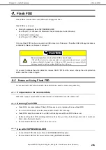
Страница 235: ...fidential information in this way If you want to change the write protection remove Flash FDD from the server change the write protection switch and then connect it again 4 1 Notes on Using Flash FDD...

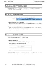
Страница 236: ...the server and then restart Boot Selection Menu shown in Chapter 3 5 2 Menus of EXPRESSBUILDER 1 Boot Selection Menu will appear 2 Insert the DVD into a computer running Windows Autorun Menu shown in...

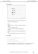
Страница 237: ...Windows b Utilities Starts a utility in EXPRESSBUILDER For details see Chapter 3 5 3 Utility in EXPRESSBUILDER c Versions Shows the versions of software and drivers in EXPRESSBUILDER d Exit Closes EXP...

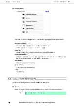
Страница 238: ...drivers and EXPRESSBUILDER c Integrated Installation Installs several applications or Starter Pack easily If the menu is not run on the server or the logon user does not have the administrator privile...

Страница 239: ...the following from a remote site through a web browser and SSH client Managing the server Operating keyboard video and mouse KVM from a remote console Accessing a CD ROM DVD ROM floppy disk ISO image...

Страница 240: ...n Guide or online help of NEC ESMPRO for details Note When you change the BMC network settings by using NEC ESMPRO Manager it may take time to complete the setting 7 3 NEC ESMPRO Agent Extension NEC E...

Страница 241: ...s of the firmware and software installed in the server with NEC ESMPRO Manager You can easily install the downloaded packages by using NEC ExpressUpdate For details see NEC ExpressUpdate Agent Install...

Страница 242: ...this utility This utility is usually installed to the C ezclct folder The log folder is created in stdclct folder and Product Info is stored in a compressed zip file Tips Log on to Windows with an ac...

Страница 243: ...rt Service Express Report Service HTTPS For details about Express Report Service Express Report Service HTTPS see Express Report Service Express Report Service HTTPS Installation Guide Windows in EXPR...

Страница 244: ...INE 3 and ExpressUpdate Agent ExpressUpdate Agent Software for performing ExpressUpdate This is installed to the server Flash FDD An optional USB device that can use as a floppy disk drive NEC ESMPRO...

Страница 245: ...Revision Record Express5800 R310g E4 R320g E4 R320g M4 Maintenance Guide Windows 245 Revision Record Document Number Date Issued Description 30 104 01 104 01 February 2019 Newly created...

Страница 246: ...R320g M4 Maintenance Guide Windows February 2019 NEC Corporation 7 1 Shiba 5 Chome Minato Ku Tokyo 108 8001 Japan NEC Corporation 2019 The contents of this manual may not be copied or altered without...

Отзывы: