background image

1. Installing Internal Optional Devices 


Express5800/E120d-M  User's Guide 

61


Chapter 2 Preparations 


Note 


Make sure that the head of a PCI card bracket is seated into the fixed slot of PCI riser 

card.  


Depending on type of PCI cards, the terminal part of the PCI card may be too large to 

fit in the connector.   


If you have trouble installing the board, remove the board once and try again. If you 

apply excessive pressure on the board, a PCI card or riser card might break. 


6.  Fix the PCI card with the screw you removed in step 4. 


Tips 

To connect a PCI card to the connector on motherboard with cable, connect a cable to PCI 
card before installing PCI riser card. 


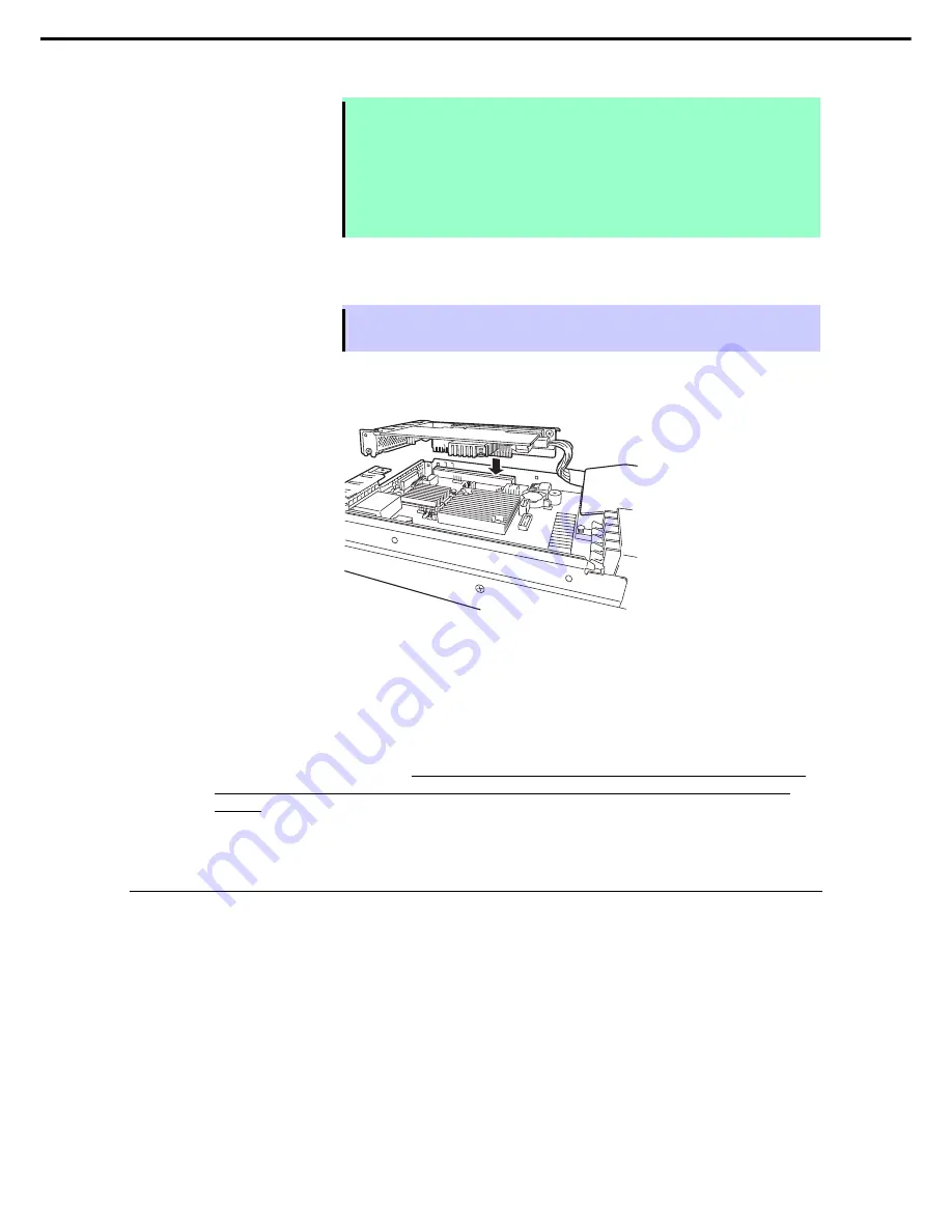
7.  Align the terminal part of the PCI riser card with the slot on the motherboard and insert it. 

Fix the PCI riser card with three screws you removed in step 2. 


8.  Continue to install or remove internal optional devices, mount and connect the server, and turn it on. 

9.  Make sure that no error messages are displayed on POST screen.   

For details on POST error messages, refer to 

Chapter 3 (1. POST Error Message)

 in "

Maintenance 

Guide

". 

10.  Run the configuration utility of the mounted card to set up the board. 

Availability or startup and operation procedure of the utility depends on card. For details, refer to the 
manual that comes with the card. 

If a PCI card including RAID Controller and LAN adapter which 

connects to any bootable device is added, the boot priority might be changed to the default 
setting.

 In that case, configure the boot priority in 

Boot

 menu of BIOS Setup Utility. For details, refer to 

Chapter 3 (2. System BIOS Setup)


1.9.4 

 Removal 

To remove a PCI card, reverse the installation procedure. 

Run SETUP and change boot order in 

Boot

 menu. Refer to 

Chapter 3 (2. System BIOS Setup)

 for how to 

specify it. 

If using the server while the card is removed, attach the blank cover that comes with the PCI riser card. 


Содержание Express5800/E120d-M

Страница 1: ...5800 Series Express5800 E120d M User s Guide 10 025 01 101 02 December 2012 2nd Edition NEC Corporation 2012 Model Number N8100 1909F 1908F Chapter 1 General Description Chapter 2 Preparations Chapter 3 Setup Chapter 4 Appendix ...

Страница 2: ... peripheral devices and ideal location for this server Chapter 3 Setting Up Your Server System BIOS configurations and summary of EXPRESSBUILDER PDF Chapter 4 Appendix Specifications and other information Installation Guide Windows Chapter 1 Installing Windows Installation of Windows and drivers and important information for installation PDF Chapter 2 Installing the Bundled Software Installation o...

Страница 3: ...neral 15 Rack installation 16 Power supply and power cord use 17 Installation relocation storage and connection 18 Cleaning and working with internal devices 19 During operation 20 Warning labels 21 External view 21 Handling precautions for proper operations 22 Chapter 1 General Description 24 1 Introduction 25 2 Accessories 26 3 Standard Features 27 3 1 Management Features 30 4 Names and Function...

Страница 4: ...rted cards and available slots 59 1 9 3 Installation 60 1 9 4 Removal 61 1 9 5 Installing RAID Controller 62 1 10 Use of Internal hard disk drives in the RAID System 64 1 10 1 Connecting cables 64 1 10 2 Notes on Building RAID System 65 1 11 Battery for RAID Controller 66 1 11 1 Handling precautions 66 1 11 2 Installing Battery 66 1 11 3 Removal 67 1 12 Hard Disk Drive 68 1 12 1 Installation 69 1 ...

Страница 5: ...Starting SETUP 88 2 2 2 Exiting SETUP 88 2 3 Description on On Screen Items and Key Usage 89 2 4 Cases that Require Configuration 91 3 EXPRESSSCOPE ENGINE 3 93 3 1 Overview 93 3 2 Network Configuration for EXPRESSSCOPE ENGINE 3 93 4 EXPRESSBUILDER 95 4 1 Features of EXPRESSBUILDER 95 4 2 Starting EXPRESSBUILDER 95 5 Installing Software Components 96 6 Turning Off the Server 97 Chapter 4 Appendix 9...

Страница 6: ...f the procedures described are not followed server failure data loss and other serious malfunctions could occur Note Indicates items that must be confirmed when handling the server or operating software Tips Indicates information that is helpful to keep in mind when using this server Hard disk drives Unless otherwise stated hard disk drives HDD described in this document refer to both of the follo...

Страница 7: ...andard Windows Server 2003 2 Windows Server 2003 Enterprise Windows 7 Professional 64 bit x64 Edition Windows 7 Windows 7 Professional 32 bit x86 Edition Windows Vista Business 64 bit x64 Edition Windows Vista Windows Vista Business 32 bit x86 Edition Windows XP Professional x64 Edition Windows XP Windows XP Professional Windows PE 3 Windows Preinstallation Environment 1 Includes 64 bit and 32 bit...

Страница 8: ... or trademarks of Adaptec Inc of the United States LSI and the LSI logo design are trademarks or registered trademarks of LSI Corporation Adobe the Adobe logo and Acrobat are trademarks of Adobe Systems Incorporated DLT and DLTtape are trademarks of Quantum Corporation of the United States PCI Express is a trademark of Peripheral Component Interconnect Special Interest Group Linux is a trademark o...

Страница 9: ...armful interference to radio communications Operation of this equipment in a residential area is likely to cause harmful interference in which case the user will be required to correct the interference at his own expense Industry Canada Class A Emission Compliance Statement This Class A digital apparatus complies with Canadian ICES 003 Avis de conformité à la réglementation d Industrie Canada Cet ...

Страница 10: ...10 WEEE Directive Chinese RoHS Vietnam RoHS Vietnam RoHS information relevant for Vietnam market Complying with CIRCULAR No 30 2011 TT BCT Hanoi August 10 2011 Temporary regulations on content limit for certain hazardous substances in electrical products ...

Страница 11: ...Regulatory Notices Express5800 E120d M User s Guide 11 Ukraine RoHS ...

Страница 12: ...r omissions please contact your retailer 5 Regardless of these 4 items NEC Corporation does not take responsibility for effects resulting from operations 6 The sample values used in this document are not the actual values Keep this document nearby so that you may refer to it as necessary Latest editions This document was created based on the information available at the time of its creation The sc...

Страница 13: ...labels WARNING or CAUTION is used to indicate a degree of danger These terms are defined as follows WARNING Indicates there is a risk of death or serious personal injury CAUTION Indicates there is a risk of burns other personal injury or property damage Precautions and notices against hazards are presented with one of the following three symbols The individual symbols are defined as follows Attent...

Страница 14: ...lectric shock or fire may be caused Do not touch the server with wet hand Otherwise an electric shock may be caused Do not touch the component specified by this symbol Otherwise an electric shock or burn may be caused Do not use the server in the place where water or liquid may pour Otherwise an electric shock or fire may be caused Do not place the server near the fire Otherwise a fire may be caus...

Страница 15: ...shock Use a rack that conforms to the designated standard This server can be mounted onto a 19 inch rack that conforms to EIA standards Do not mount the server onto any rack that does not conform to EIA standards Doing so may cause a server malfunction personal injury or damage to peripheral devices For more information about racks that can be used with the server consult with your maintenance ser...

Страница 16: ...ponents such as the door or rails When installing the door make sure that both upper and lower hinge pins are held in place Incomplete attachment may cause components to fall off as well as personal injury Do not extend any device from the rack that is not stabilized When extending a device from the rack make sure that the rack is stable by using a stabilizer or seismic reinforcement Otherwise the...

Страница 17: ...ngle outlet by using extension cords The electric current exceeding the rated flow overheats the outlet which may cause a fire Insert the power plug into the outlet as far as it goes Heat generation resulting from a halfway inserted power plug imperfect contact may cause a fire Heat will also be generated if condensation is formed on dusty blades of the halfway inserted plug increasing the possibi...

Страница 18: ... specified Do not install the server in the following places or any place other than specified in this User s Guide Failure to follow this instruction may cause a fire A dusty place A humid place such as near a boiler A place exposed to direct sunlight An unstable place Do not use the server in an environment where corrosive gas is present Do not install the server in a place subject to corrosive ...

Страница 19: ... the server with loose cable connections Do not use any damaged cable Cleaning and working with internal devices WARNING Do not disassemble repair or alter the server Never attempt to disassemble repair or alter the server on any occasion except as described in this document Failure to follow this warning may cause not only malfunction of the server but also an electric shock or fire Do not attemp...

Страница 20: ...ly separating the server from the rack may result in personal injury Avoid contact with the server during thunderstorms Do not touch any part of the server including the cables when a thunderstorm is approaching Also do not connect or disconnect any devices There may be a risk of electric shock from lightning strike Keep animals away from the server Keep animals such as pets away from the server P...

Страница 21: ...ntial hazards This label is either attached or printed on the component to draw attention from users to potential hazards involved in handling the server Do not remove or black out this label and keep it clean If no label is attached or printed on the server or if there is a label coming off or stained contact your sales representative External view ...

Страница 22: ...r details about cleaning Momentary voltage drop may occur due to lightning strike To prevent this use of UPS is recommended In the following cases check and adjust the system clock before operation After transportation After storage After the server is used following a period of disuse in which storage conditions did not conform to those that guarantee server operations temperature 40 C humidity 2...

Страница 23: ... from reflecting bright lights and to make the display contents easy to see Working without adjusting the display to a comfortable angle makes it difficult for you to maintain a proper posture and you will get tired easily Adjust the viewing angle before use Adjust the brightness and contrast of the display Display screens have functions to control brightness and contrast The most suitable brightn...

Страница 24: ...the features of this server and the name of each part 1 Introduction 2 Accessories Verify the condition of your server s accessories 3 Standard Features This section describes the server s features and the server management 4 Names and Functions of Parts This section describes the name of each part contained in this server ...

Страница 25: ...processor NEC s latest technology and architectures realize high power and high speed operation that cannot be matched by existing servers The server is designed with consideration of not only reliability but also expandability which enables you to use it as a network server Read this document before using the server thoroughly to fully understand handling of Express5800 Series Server and apprecia...

Страница 26: ...ories which are required for setup or maintenance Make sure you have them all for future use Notes on Use Getting Started Make sure you have all accessories and inspect them If an accessory is missing or damaged contact your sales representative Important The chassis serial number plate and maintenance label is located on the server ...

Страница 27: ...30 2 20GHz 6Core N8100 603F Intel Xeon processor E5 2430L 2 00GHz 6Core N8100 604F Intel Xeon processor E5 2450L 1 80GHz 8Core N8100 605F Intel Xeon processor E5 2470 2 30GHz 8Core Turbo Boost Technology feature 1 Hyper Threading Technology feature 1 High speed memory access DDR3L 1600 supported 2 High speed disk access SATA SAS 6Gbps supported High speed 1000BASE T 100BASE TX 10BASE T 2 ports int...

Страница 28: ...eature 80 PLUS Platinum certified high efficiency power supply Fan control appropriate to environment work load and configuration Silent sound design Enhanced Intel SpeedStep Technology supported Cold redundant feature Expandability per one server module High speed option slot PCI Express 3 0 x16 lane 1 slot Low Profile Large capacity memory of up to 384 GB 3 Can upgrade to multi processor system ...

Страница 29: ...Self Test POST Test and Diagnosis T D utility Easy setup BIOS Setup utility SETUP EXPRESSBUILDER Setup utility Maintenance features Allows access from front of the chassis to insert or remove the server module Replacement of server module can be performed easily Off line Tools Memory dump feature using DUMP Switch Feature to back up and restore BIOS BMC configuration information using EXPRESSSCOPE...

Страница 30: ...o Monitors temperatures fans voltage power supply and others Temperature Monitors the temperature inside of the chassis Fan Monitors the fans Voltage Monitors the voltage inside of the chassis System environment Power supply Monitors the power supply unit Software Shows service driver and OS information Network Shows network LAN information and monitors packets BIOS Shows BIOS information Local po...

Страница 31: ...the USB interface 6 BMC RESET Switch The switch to reset BMC of this server Use the switch only when there is a problem with EXPRESSSCOPE Engine 3 BMC To use this switch press it at least five seconds 7 DUMP Switch NMI When DUMP Switch is pressed memory dump is performed 8 Unit ID UID Switch LED The switch to turn on and off UID LED Pressing the switch once turns on UID LED and pressing again turn...

Страница 32: ...rom the point of performance and security because LAN port 1 may receive both data 7 SPEED LED The LED indicates the transfer speed of LAN ports 4 6 5 8 Management LAN connector LAN connector which supports 100BASE TX 10BASE T This port cannot be used as a data transmission port This port is used for connecting to EXPRESSSCOPE Engine 3 9 Serial port COM connector This connector is used to connect ...

Страница 33: ...4 Names and Functions of Parts Express5800 E120d M User s Guide 33 Chapter 1 General Description 4 3 External View ...

Страница 34: ...rnal View Server Module Left 1 Front Panel Board 2 HDD BP 3 Cooling fans 1 FAN1F R 2 FAN2F R 3 FAN3F R 4 FAN4F R 4 Processor CPU Mounted under the heat sink 5 DIMM Option 6 Motherboard 7 Riser card 8 Node BP 9 Battery tray for RAID Controller 10 2 5 inch drive bay 3 4 3 3 3 2 4 1 4 2 5 5 6 7 8 9 10 1 2 3 1 ...

Страница 35: ...Server Module Right 1 Front Panel Board 2 HDD BP 3 Cooling fans 1 FAN1F R 2 FAN2F R 3 FAN3F R 4 FAN4F R 4 Processor CPU Mounted under the heat sink 5 DIMM Option 6 Motherboard 7 Riser card 8 Node BP 9 Battery tray for RAID Controller 10 2 5 inch drive bay 3 2 4 1 5 6 7 8 10 1 2 3 1 3 4 3 3 4 2 5 9 ...

Страница 36: ...r CMOS Jumper switch 9 Clear Password Jumper switch 10 Connector for USB memory module 11 SPI Mezzanine connector EXPRESSSCOPE Profile Key SPI flash memory has been installed where BIOS and BMC configuration data is stored Relocate it when replacing motherboard to inherit configuration data 12 Front video connector 13 PCI Riser Card connector for low profile card For the supported card specificati...

Страница 37: ...lure The following table lists STATUS LED patterns their explanation and solution Tips If you have installed NEC ESMPRO you can view error logs to check the causes of failures STATUS LED pattern Explanation Solution On green The server works normally Memory is in a degraded state A correctable memory error has often occurred Operating while CPU error is detected Flashing green In redundant power c...

Страница 38: ...d Check if the internal fan cable is properly connected If the LED indication does not change contact your sales representative A temperature warning was detected Check the internal fan for dusts Also check if the fan unit is properly connected If the LED indication does not change contact your sales representative A voltage warning was detected Flashing amber One or more hard disk drives are brok...

Страница 39: ... Contact your sales representative Flashing green and amber alternately only when RAID system is configured Rebuild is in progress When the failed hard disk drive is replaced rebuild process starts automatically auto rebuild feature Off Hard disk drive is halted Important Observe the following precautions whenever you use the auto rebuild feature Do not turn off or reboot the server while a HDD is...

Страница 40: ...r is connected with network normally Flashing green The server is accessing network Off The server is disconnected from network SPEED LED 1 2 M This LED indicates which network interface is used Two onboard LANs 1 2 support 1000BASE T 100BASE TX and 10BASE T Management LAN M supports 100BASE TX and 10BASE T The following table lists LINK ACT LED patterns and their explanation SPEED LED pattern Exp...

Страница 41: ...eir explanation AC POWER LED pattern Explanation Solution On green The server is powered on The power cord is connected and AC power is supplied Flashing green Cold Redundant feature is enabled The power cord is not connected in redundant power configuration Connect the power cable On amber Power unit is failing Contact your sales representative Flashing amber Power unit is failing Contact your sa...

Страница 42: ...This chapter describes preparations for using this server 1 Installing Internal Optional Devices You can skip this section if you did not purchase any optional devices 2 Installation and Connection You must place the server in a suitable location and connect some cables following this section ...

Страница 43: ...l and remove optional devices properly and safely WARNING Be sure to observe the following precautions to use the server safety Failure to observe the precautions may cause death or serious injury For details refer to Safety precautions in Precautions for Use Do not disassemble repair or modify the server Do not remove the lithium battery NiMH battery or Li ion battery Disconnect the power plug wh...

Страница 44: ...by periodically touching a metal surface while working on the components Select a suitable work space Work with the server on the anti static or concrete floor If you work with the server on a carpet where static electricity is likely to be generated be sure to take anti static measures beforehand Use a work table Place the server on an anti static mat to work with Clothing Do not wear wool or syn...

Страница 45: ...et server Refer to Chapter 2 1 4 Identifying Servers UID Switch 2 If the server module is ON turn it off Refer to Chapter 3 1 Turning on the Server 3 Remove the server module from the server enclosure and put it on a flat rigid desk Refer to Chapter 2 1 5 Removing Server Module for details If you remove the server module from module enclosure wait at least 30 seconds before insert it again into en...

Страница 46: ...itch Using UID Unit ID Switch helps you to identify the target server When the server is working or before you turn the server off or disconnect a cable from the server be sure to identify the target server by using UID Switch first To turn UID LED on press UID Switch When it is pressed again the LED will be off M NMI UID switch ...

Страница 47: ...M Memory Processor CPU PCI card LAN riser card RAID Controller Extra battery for RAID Controller 1 Refer to steps 1 to 3 in Chapter 2 1 3 Overview of Installation and Removal for preparations 2 Lift the lever while pushing the locking mechanism toward right Hold the handle and pull out the server module horizontally Important If you remove the server module from module enclosure wait at least 30 s...

Страница 48: ...lures or damage resulted from installing such a processor will be charged Tips When a processor is additionally installed Windows may log the system event on System Viewer however it is no problem for operation 1 6 1 Installation Follow steps below to install the processor 1 Refer to steps 1 to 3 in Chapter 2 1 3 Overview of Installation and Removal for preparations 2 Locate the CPU socket to whic...

Страница 49: ...tch is aligned with the key on the CPU socket Important Be sure to hold the processor only at the edges Pay attention not to touch the bottom of the processor pin section Note Insert the processor while aligning the notch on the processor with the key on the CPU socket Bring down the processor straight without tilting or sliding it in the socket 7 Lightly push the processor to the CPU socket and c...

Страница 50: ...erboard Important Use the heat sink that comes with your server when you install the CPU1 Basic Need the additional heat sink N8101 609F when you install the CPU2 Optional Note Make sure the location to put the heat sink 10 Make sure that the heat sink is installed on a level with the motherboard Note If the heat sink is not level remove it and then install it again The following probably causes t...

Страница 51: ...nance Guide Advanced Processor Configuration Processor Information CPU ID L2 Cache RAM L3 Cache RAM 1 6 2 Replacement Removal To remove processor CPU reverse the installation procedure Important Do not remove any processor unless it is failed To remove the heat sink from the processor first turn the heat sink to the left and right lightly to make sure that the heat sink can be apart from the proce...

Страница 52: ...on each module 1 7 1 Maximum supported memory size The maximum available memory size on the server depends on the basic architecture x86 architecture and OS specs List of maximum memory sizes OS The maximum DIMM capacity supported on each OS The maximum DIMM capacity supported on the server Microsoft Windows Server 2008 Standard 4GB 4GB Microsoft Windows Server 2008 Standard x64 Microsoft Windows ...

Страница 53: ...Kit 800MHz E5 2430 2430L embedded model N code and product name Memory clock speed Number of memory boards per memory channel 1 2 N8102 504F 2GB DDR3 1600 UNB Memory Kit N8102 505F 4GB DDR3 1600 UNB Memory Kit 1333MHz 1066MHz N8102 506F 8GB DDR3 1600 REG Memory Kit N8102 507F 16GB DDR3 1600 REG Memory Kit 1333MHz N8102 508F 32GB DDR3 1600 REG Memory Kit 800MHz E5 2470 2450L embedded model N code a...

Страница 54: ...allest slot number of each CPU Installation order depends on combination of DIMMs to be installed See the table below to find allowable combination of DIMMs and install DIMMs starting from the largest capacity and from the smallest slot number N8102 N code 504F 505F 506F 507F 508F N8102 504F N8102 505F N8102 506F N8102 507F N8102 508F Allowed to be install together Not allowed to be install togeth...

Страница 55: ...e displayed refer to Chapter 3 1 POST Error Message in Maintenance Guide 5 Run BIOS Setup Utility and select Memory Configuration and then Memory Information from the Advanced menu Make sure the capacity of added DIMM is displayed properly Refer to Chapter 2 1 System BIOS in Maintenance Guide 6 Select Memory Configuration from the Advanced menu and then specify Yes for Memory Retest After that sel...

Страница 56: ... LAN Riser Card Important You must avoid static electricity to work with the procedure below For details refer to Chapter 2 1 2 Anti static Measures 1 8 1 Installation Follow steps below to install LAN Riser Card 1 Refer to steps 1 to 3 in Chapter 2 1 3 Overview of Installation and Removal for preparations 2 Remove the three screws from bracket and remove bracket 3 Remove the three screws from the...

Страница 57: ...curely 6 Secure the bracket of LAN Riser Card with two screws you have removed in step 2 7 Install the port cover provided with LAN Riser Card and secure it with four screws you have removed in steps 2 and 3 1 8 2 Removal Remove LAN Riser Card in reverse order of installation steps Important To maintain the cooling effect in the server install the blank cover in the vacant LAN Riser Card slot ...

Страница 58: ... location of PCI device by PCI bus number device number and function number shown in the table below PCI device Bus number Device number Function number Onboard LAN1 08h 0 0 Onboard LAN2 08h 0 1 PCI slot Low Profile 20h 0 X LAN riser card slot 10h 0 X If an additional LAN card is installed it is hard to push the catch of the connector with your finger that is connected to the LAN card Disconnect t...

Страница 59: ...0 154 Fibre Channel Controller 2ch 8Gbps Optical Card performance PCI Express2 0 x8 Dedicated to connect with external Fibre Channel devices N8104 138 1000BASE T Adapter Card performance PCI Express2 0 x1 For additional LAN port Card type PCI Express 2 0 x4 N8104 132 1000BASE T Adapter 2ch Card performance PCI Express2 0 x1 For additional LAN port Card type PCI Express 2 0 x4 N8104 133 1000BASE T ...

Страница 60: ...Overview of Installation and Removal for preparations 2 Remove the three screw securing the rise card Hold the both ends of the PCI riser card and lift it straight to remove it 3 Confirm the slot to install a card with the reference to the table on 1 9 2 Supported cards and available slots 4 Remove a screw from the PCI rise card and remove the blank cover Note Keep the removed blank cover for futu...

Страница 61: ...nstall or remove internal optional devices mount and connect the server and turn it on 9 Make sure that no error messages are displayed on POST screen For details on POST error messages refer to Chapter 3 1 POST Error Message in Maintenance Guide 10 Run the configuration utility of the mounted card to set up the board Availability or startup and operation procedure of the utility depends on card F...

Страница 62: ... BIOS Setup utility select PCI Configuration from the Advanced menu and then make sure that the parameter of PCI Slot xx Option ROM xx is PCI slot number is set to Enabled When connecting a RAID Controller set the boot priority to 8th or higher in the Boot menu of the BIOS Setup utility If the setting is 9th or lower the configuration menu for RAID Controllers cannot be launched Take the following...

Страница 63: ...I riser card insert RAID Controller into the slot completely 6 Disconnect SAS cable from SAS connector on motherboard and connect that cable to PORT 0 3 connector on RAID Controller 7 Align the terminal pins of PCI riser card with the slot on motherboard insert PCI riser card into the slot completely 8 Fix the PCI riser card with the screw you removed in Step 2 ...

Страница 64: ...ackup the hard disk drive before installing the RAID Controller and configuring the RAID System Note In the RAID System use hard disk drives that have the same specifications capacity rotational speed and standard for each Disk Array Tips Logical Drives can be created even with only one Physical Device If using internal hard disk drives in RAID System with an optional RAID Controller N8103 149 150...

Страница 65: ...uild a RAID System RAID level N8103 149 N8103 150 151 RAID 0 1 1 RAID 1 2 2 RAID 5 3 RAID 6 3 RAID 10 4 4 In the RAID System all the hard disk drives SAS SATA or SSD must have the same capacity interface type and rotational speed Use RAID System Configuration utility WebBIOS to build a RAID System For more information refer to the manual supplied with the optional RAID Controller N8103 149 150 151...

Страница 66: ...AID Controller you are using The battery is a very delicate electronic device Before installation touch the metal frame part of the server to discharge the static electricity from your body Do not drop or bump the battery For recycling and disposing of the battery refer to the User s Guide that comes with it 1 11 2 Installing Battery This section describes the procedure of installing a battery for...

Страница 67: ... the battery tray for RAID Controller to the server chassis and secure it with two screws you removed in Step 3 6 Connect the cable of extra battery to RAID Controller 1 11 3 Removal For removing the battery for the RAID Controller reverse the installation procedure Route the cable along the side of chassis ...

Страница 68: ...d disk drive might cause a failure of the server as well as the hard disk drive Note the following precautions to install hard disk drives Hard disk drives having different capacities interface types or rotational speeds cannot be installed together Hard disk drives cannot be installed together with SSD in the specific RAID System To use the hard disk drives as array disk you may need to change ju...

Страница 69: ...fications capacity rotational speed and standard 1 Refer to steps 1 to 3 in Chapter 2 1 3 Overview of Installation and Removal for preparations 2 Locate the bay where you are going to install the hard disk drive The server provides 4 bays Install hard disk drives in ascending port number order 3 Remove the dummy trays Dummy trays are installed in all bays except for bay 0 Note Keep the dummy trays...

Страница 70: ... tray firmly with both hands 6 Slowly close the handle The tray is locked making a clicking sound Note When you push the drive into the bay confirm the handle got hooked on the frame 7 Turn on the server run SETUP utility and then specify the boot order from the Boot menu For details about the Boot menu refer to Chapter 2 1 2 5 Boot in Maintenance Guide Tips The stored boot order is cleared when a...

Страница 71: ...ystem BIOS Setup 1 12 3 Replacing a hard disk drive in the RAID System Auto Rebuild In the RAID System you can use the auto rebuild feature to restore data back to the state before a failure occurred The auto rebuild feature is enabled in logical drives set to RAID 1 RAID 5 RAID 6 or RAID 10 The disk is automatically rebuilt when hot swapping replacing a disk while the power on a failed hard disk ...

Страница 72: ...n run the system with optimum power efficiency by raising operating efficiency of primary power supply unit and lowering that of redundant power supply unit in redundant power configuration If power efficiency of power units is not optimized due to system configuration this feature is disabled automatically Cold redundant feature can be used under the following conditions Two power supply units mu...

Страница 73: ...ic hazard Important Do not remove a power supply unit operating normally Tips In redundant power system is configured using two power supply units the failed power supply unit can be replaced while the system is powered on Remove the power supply unit in the following procedure 1 Refer to steps 1 to 2 in Chapter 2 1 3 Overview of Installation and Removal for preparations 2 Disconnect the AC power ...

Страница 74: ... another power supply unit goes on amber When the power cords are connected AC POWER LEDs on both power supply units light green 6 Confirm by the STATUS LED or on the POST screen that there are no errors related to the power supply units Refer to Chapter 3 1 POST Error Message in the Maintenance Guide for details on the error messages If the AC POWER LEDs are off reinstall the power supply units I...

Страница 75: ...nly in the specified environment Do not connect the ground wire to a gas pipe CAUTION Be sure to observe the following precautions to use the server safely Failure to observe the precautions may cause burns injury and property damage For details refer to Safety precautions in Precautions for Use Do not carry or install the server only by a single person Do not install the server so that the load m...

Страница 76: ...de nitrogen dioxide chlorine ammonia ozone etc exist Place where the air or dust includes components accelerating corrosion ex sulfur sodium chloride or conductive metals Place where chemicals may be accidentally sprayed over Place where a carpet not subject to anti static process is laid Place where some objects may be fallen on the rack Place near a device generating intense magnetic field such ...

Страница 77: ...cautions to use the server safely Failure to observe the precautions may cause burns injury and property damage For details refer to Safety precautions in Precautions for Use Do not drop Do not leave the server being pulled out Do not install with the cover removed Do not get your fingers caught Important Temperature increases and airflow in the rack If multiple devices are installed or if the ins...

Страница 78: ...LEFT to the left side of rack 2 Engage the angle protrusion of rail with the hole on 19 inch rack Mount the rail while pushing the locking mechanism until it is securely locked The figure below shows the front left side Mount rails on rear left side front right side and rear right side in similar way The height of rails mounted on left and right sides must be level Important Confirm that the rails...

Страница 79: ...d property damage For details refer to Safety precautions in Precautions for Use Do not lift the server with two or less persons Do not drop Do not leave the server being pulled out Do not install with the cover removed Do not get your fingers caught 1 Installation Mount the server to a rack in the following procedure Important Always install the server with three or more persons 1 Push the server...

Страница 80: ... carefully Important Be careful not to get your fingers caught in the rails or lever 3 Hold the server firmly and remove it from the rack Important While more than three persons are supporting the bottom part of the server slowly pull out the server Do not apply load on the server from top when it is being pulled out Doing so cause the server to drop 3 Removing Rails Remove rails from the rack in ...

Страница 81: ... death or serious injury For details refer to Safety precautions in Precautions for Use Do not hold the power plug with wet hands Do not connect the ground wire to a gas pipe CAUTION Be sure to observe the following precautions to use the server safely Failure to observe the precautions may cause burns injury and property damage For details refer to Safety precautions in Precautions for Use Use on...

Страница 82: ...nit Finally connect the provided power cord to an outlet 1 For connecting with UPS refer to the next section Hub switching hub Hub switching hub 1000BASE T 100BASE TX 10BASE T 1000BASE T 100BASE TX 10BASE T 100BASE TX 10BASE T Ports for data transmission Ports for data transmission Management LAN port Device with serial interface Hub switching hub 1 Connect the power cord to a circuit breaker of u...

Страница 83: ...wer supply UPS To connect the power cord of the server to the uninterruptible power supply UPS use the connector output on the rear of the UPS For details refer to the manual supplied with the UPS When the power cord is connected to a UPS the BIOS settings may need to be changed in order to link the server with the power supply from the UPS To change the settings select Server and then AC LINK in ...

Страница 84: ...IOS Setup You can customize the BIOS settings by following the instructions in this section 3 EXPRESSSCOPE Engine 3 EXPRESSSCOPE Engine 3 provides useful features through the Baseboard Management Controller BMC 4 EXPRESSBUILDER EXPRESSBUILDER helps you to maintain the server 5 Installing Software Components Describes the installation of bundled software 6 Turning off the Server Turn off power when...

Страница 85: ...1 Turn on the peripheral devices and display monitor Note If the power cord is connected to power control system such as an Uninterruptible Power Supply UPS make sure that the power control system is turned on 2 Press the POWER switch at the front of the server The POWER LED is turned on green and after a while the logo appears on the display Important Do not connect or disconnect USB device while...

Страница 86: ...urity menu of SETUP you will be prompted to enter password after the logo is displayed If you enter the incorrect password three times consecutively POST aborts You can no longer proceed In this case power off the server and power it on Important Do not set a password before OS is installed 3 If Esc key is pressed the logo disappears and the details of POST are displayed Tips If Quiet Boot is Disa...

Страница 87: ... Depending on the configuration the message Press Any Key might appear to prompt a key entry This is a behavior of the BIOS of the optional board Continue to operate after checking the manual of the optional board 7 The OS starts when POST is completed 1 1 2 POST error messages When POST detects an error it displays an error message on the screen or beeps for some errors For descriptions of error ...

Страница 88: ...ge appears on the lower left of the screen On screen message depends on your system environment Press F2 SETUP F4 ROM Utility F12 Network If you press F2 key at this time SETUP runs and displays Main menu upon completion of POST You can also press F2 key while expanding option ROM to display Main menu Tips If password is set you will be prompted to enter password at next startup of SETUP The timin...

Страница 89: ...ter key Press this key to confirm the selected parameter Esc key Cancel the pop up menu Pressing this key on submenu screen takes you to the previous screen If you keep pressing the key the following window is displayed If you select Yes the SETUP closes without saving the changed parameters Quit without saving Yes No F1 key Press this key to display help information If you need help using the SET...

Страница 90: ... Yes restore the parameters of the currently selected item to the default setting This might be different from the parameters configured before shipment Load Setup Defaults Yes No F4 key If you press this key the following window appears If you select Yes the parameter you configured is saved and SETUP closes Save configuration and exit Yes No ...

Страница 91: ... slot number of the option board Change the boot order of devices Boot Boot Option Priorities Change the boot priority When you use EXPRESSBUILDER set CD DVD to the highest priority Use remote power on function via modem Advanced Advanced Chipset Configuration Wake On Ring Enabled Use remote power on function via RTC alarm Advanced Advanced Chipset Configuration Wake On RTC Alarm Enabled Boot Use ...

Страница 92: ... password 3 times operation stops You cannot operate further Turn off the power Saving changes If you finish configuration select Save Exit and then Save Changes and Exit to save changes and exit If you wish to exit without saving the changed parameters select Save Exit and then Discard Changes and Exit Or if you wish to restore the setting to default values select Save Exit and then Load Setup De...

Страница 93: ...Remote FD Remote CD DVD Remote USB Memory or Virtual Flash is always connected as USB mass storage 3 2 Network Configuration for EXPRESSSCOPE ENGINE 3 To enable EXPRESSSCOPE Engine 3 to be used via network network configuration is required Below is an example of the configuration procedure which enables EXPRESSSCOPE Engine 3 to be used via a web browser 1 Run POST following Chapter 3 1 1 1 POST se...

Страница 94: ...ddress Subnet Mask Tips If Shared BMC LAN is enabled Web feature remote media KVM feature or command line interface feature may be interrupted In this case wait for a while and connect with network again 6 Connect the LAN cable to the management LAN connector in order to connect to the network It will be available for use if you access EXPRESSSCOPE Engine 3 via Web browser from management PC accor...

Страница 95: ...n the menu after boot Bundled software Stores various bundled software such as NEC ESMPRO Agent Maintenance Diagnoses your server system To use this feature select Tool menu on the top menu after boot Document Stores various documents including this User s Guide 4 2 Starting EXPRESSBUILDER Set the DVD on the drive and either turn on the server or restart the server by pressing Ctrl Alt Delete EXPR...

Страница 96: ...er 3 Setup 5 Installing Software Components Continue to install software components such as OS Refer to the following document and follow instructions Installation Guide Windows Tips Hibernate function of Windows Server cannot be used Do not set Hibernate at Windows shutdown ...

Страница 97: ...ied with the UPS or the documentation for the application controlling the UPS 1 Shut down the OS 2 The server automatically turns off after the OS shuts down Confirm that POWER LED is OFF DC OFF state 3 Turn off peripheral devices 4 AC power of server module is turned off only if it is removed from module enclosure Important If you removed a server module from module enclosure wait at least 30 sec...

Страница 98: ...Express5800 E120d M User s Guide 98 NEC Express5800 Series Express5800 E120d M Appendix 1 Specifications 2 Interrupt Lines ...

Страница 99: ...ted to LAN riser card Chip VideoRAM Management controller chip 32 MB Graphics Graphic display resolution 16 770 000 colors 640 x 480 800 x 600 1 024 x 768 1 280 x 1 024 Interface 3xUSB 2 0 2x Front x1 Internal 1x Analog RGB Mini D sub 15 pin 1x Front 1x Serial port RS 232C compliant D sub 9 pin Serial Port A 1x Rear 2x1000BASE T LAN connector 1000BASE T 100BASE T 10BASE T RJ45 2x Rear 1x Managemen...

Страница 100: ...his table as a reference when you add optional devices Interrupt lines As factory settings interrupt lines are assigned as follows IRQ Peripheral Device Controller IRQ Peripheral Device Controller 0 System timer 12 1 13 Numeric data processor 2 14 3 COM 2 serial port 15 4 COM 1 serial port 16 USB 5 PCI 17 6 18 7 19 SATA 8 Real time clock 20 9 21 10 22 11 23 USB ...

Отзывы: