

Portrait 824
Each Auxiliary PCB supports two Door Boxes. In addition, you can connect each circuit’s control relay to an electric door strike.
This allows an extension user to remotely activate the door strike while talking to a visitor at the Door Box. The control relays are
normally open.
1. Loop the cable from the miscellaneous block once through a ferrite bead
(supplied with the Auxiliary PCB) then plug the DDK connector into the
Door Box (1 or 2) connector on the Auxiliary PCB. The first Door Box is
labeled DH1 on the PCB. The second Door Box is labeled DH2. If using
both Door Boxes, loop both cables through the same ferrite bead.
Note: The ferrite bead should be placed as close as possible to the PCB.
2. Use VR3 or VR4 to adjust the volume of the Door Box. VR3 corresponds
to Door Box 1, VR4 corresponds to Door Box 2.
3. Refer to the system’s software manual for programming information.
28i/124i
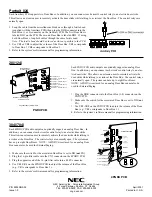
Each PGDU PCB audio output can optionally support an analog Door
Box. In addition, you can connect each circuit’s control relay to an elec-
tric door strike. This allows an extension user to remotely activate the
door strike while talking to a visitor at the Door Box. The control relays
are normally open. The system can have up to eight Door Boxes.
NOTE: A PGDU circuit used for an analog Door Box cannot also be
used for External Paging.
1. Plug the DDK connector into the Door Box (1-4) connector on the
PGDU PCB.
2. Make sure the switch for the associated Door Box is set to DH (not
PG).
3. Use VR1-VR4 on the PGDU PCB to adjust the volume of the Door
Box (e.g., VR1 corresponds to Door Box 1).
4. Refer to the system’s software manual for programming information.
384i/704i
Each 4PGDU PCB audio output can optionally support an analog Door Box. In
addition, you can connect each circuit’s control relay to an electric door strike.
This allows an extension user to remotely activate the door strike while talking to
a visitor at the Door Box. The control relays are normally open. The system can
have up to eight Door Boxes. NOTE: A 4PGDU circuit used for an analog Door
Box cannot also be used for External Paging.
1. Make sure the switch for the associated Door Box is set to DH (not PG).
2. Plug the 16-pin filter cable into the CN1 connector on the 4PGDU PCB.
3. Plug the opposite end of the 16-pin filter cable into a 48FU connector.
4. Use VR1-VR4 on the 4PGDU PCB to adjust the volume of the Door Box
(e.g., VR1 corresponds to Door Box 1).
5. Refer to the system’s software manual for programming information.
P/N 92245INS02
Issue 1-0
NEC America Inc., Corporate Networks Group
4 Forest Parkway, Shelton, CT 06484
TEL: 203-926-5400 FAX: 203-929-0535
cng.nec.com
April 2001
Printed in U.S.A.
92001
-
43
Page/Door Box (PGDU) PCB
Mode Switches
for each circuit
Door Box / External Page
Volume Controls
DH
CN3
CN
4
DH
DH
DH
PG
PG
PG
PG
1
2
3
4
VR1
Door Box 4 - External Page 4
Door Box 3 - External Page 3
Door Box 2 - External Page 2
Door Box 1 - External Page 1
Control Relay 4
Control Relay 3
Control Relay 2
Control Relay 1
VR2
VR3
VR4
9 2 0 0 0
- 1 5
CN1
CN2
VR1
VR2
VR3
VR4
Door Box and
Paging Circuits
Page/Doorbox PCB
Fax and Alarm
Sensors
Status LED
(Normally flashing)
Door Box/External Paging Zone
1 Volume Control
Door Box/External Paging Zone
2 Volume Control
Door Box/External Paging Zone
3 Volume Control
Door Box/External Paging Zone
4 Volume Control
Use non-metallic
alignment tool
To 48FU
Filter Unit
To 48FU
Filter Unit
DH
Door Box/
Page Circuit 1
Door Box/
Page Circuit 2
Door Box/
Page Circuit 3
Door Box/
Page Circuit 4
DH
PG
External Page
Circuit
Door Box
Circuit
PG
PGDU PCB
4PGDU PCB


