background image

English-6

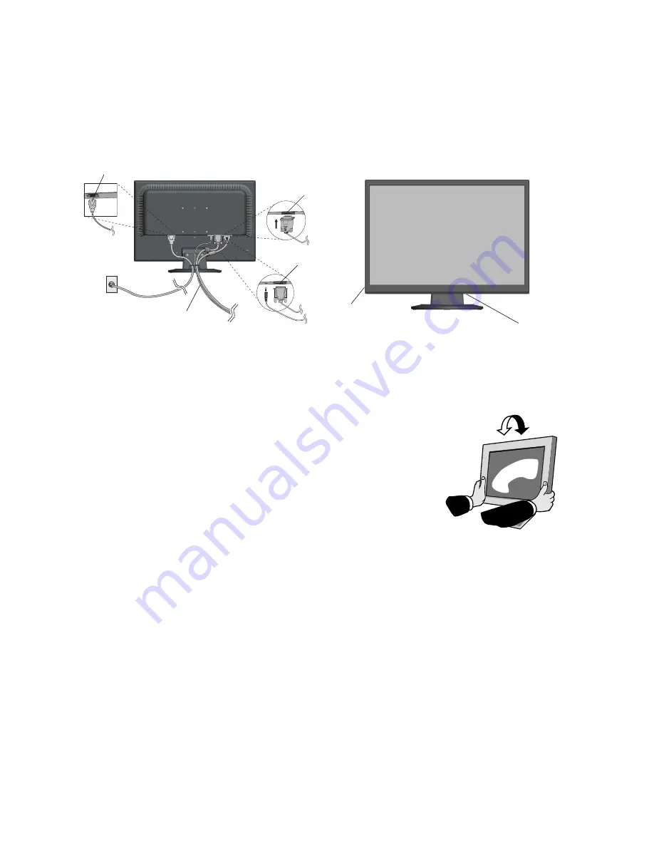
3. Connect the 15-pin mini D-SUB of the video signal cable and Audio Cable to the appropriate connector on the back of

the monitor (

Figure B.1

). Connect the Headphone (not included) to the appropriate connector at the left of the monitor

(

Figure C.1

).

4. Connect one end of the power cord to the monitor and the other end to the power outlet. Place the Video Signal Cable and

power cord to the Cable holder (

Figure B.1

).

NOTE:

Adjust position of cable placed to the Cable holder to avoid damage for cable or monitor.

NOTE:

Please refer to Caution section of this manual for proper selection of power cord.

5. Turn on the monitor with the bottom power button and the computer (

Figure C.1

).

Figure B.1

Headphone

Figure C.1

Power Button

6. No-touch Auto Adjust automatically adjusts the monitor to optimal settings upon initial setup for most timings.

For further adjustments, use the following OSD controls:

• Auto Adjust Contrast

• Auto Adjust

Refer to the 

Controls 

section of this User’s Manual for a full description of these OSD

controls.

NOTE:

If you have any problem, please refer to the 

Troubleshooting

 section of this

User’s Manual.

Tilt

Grasp both sides of the monitor screen with your hands and adjust the tilt as desired
(

Figure TS.1

).

Remove Monitor Stand for Mounting

To prepare the monitor for alternative mounting purposes:

1. Disconnect all cables.

2. Place monitor face down on a non-abrasive surface (

Figure R.1

).

3. Remove the 2 screws connecting the monitor to the stand and remove the stand as indicated (

Figure R.2

).

The monitor is now ready for mounting in an alternative manner.

4. Connect the AC cord and signal cable to the back of the monitor (

Figure R.3

).

5. Reverse this process to re-attach stand.

NOTE:

Use only VESA-compatible alternative mounting method.

NOTE:

Handle with care when removing monitor stand.

Figure TS.1

Power cable

Input (Audio)

Input (DVI)

Input (VGA)

Содержание AS231WM-BK

Страница 1: ...AccuSync AS231WM User s Manual...

Страница 2: ...English 1 Recommended use English 3 Contents English 5 Quick Start English 5 Controls English 8 Specifications English 11 Features English 12 Troubleshooting English 13 TCO Displays 5 0 English 14 Ma...

Страница 3: ...REFER SERVICING TO QUALIFIED SERVICE PERSONNEL Declaration of the Manufacturer We hereby certify that the colour monitor AccuSync AS231WM L239NK is in compliance with Council Directive 2006 95 EC EN 6...

Страница 4: ...ase the separation between the equipment and receiver Connect the equipment into an outlet on a circuit different from that to which the receiver is connected Consult your dealer or an experienced rad...

Страница 5: ...g Immediately unplug your monitor from the wall outlet and refer servicing to qualified service personnel under the following conditions When the power supply cord or plug is damaged If liquid has bee...

Страница 6: ...image persistence after image effects Get regular eye checkups Ergonomics To realize the maximum ergonomics benefits we recommend the following Use the preset Size and Position controls with standard...

Страница 7: ...locking button on the Base Stand should fit into the hole on the Stand Figure S 1 To attach the AccuSync LCD monitor to your system follow these instructions 1 Turn off the power to your computer 2 F...

Страница 8: ...most timings For further adjustments use the following OSD controls Auto Adjust Contrast Auto Adjust Refer to the Controls section of this User s Manual for a full description of these OSD controls NO...

Страница 9: ...se use screws 4pcs as shown in the picture when installing To meet the safety requirements the monitor must be mounted to an arm which guaranties the necessary stability under consideration of the wei...

Страница 10: ...Cursor goes to left Cursor goes to right At OSD showing Adjustment stage Go to Icon selection stage Adjust value decrease or Cursor for adjust goes to left Adjust value increase or Cursor for adjust...

Страница 11: ...ontal Image Position within the display area of the LCD DOWN UP Analog input only Controls Vertical Image Position within the display area of the LCD H SIZE Analog input only Adjusts the horizontal si...

Страница 12: ...ing value of Carbon foot print Carbon meter value is updated each 5 min SIGNAL INFORMATION If you select ON monitor displays VIDEO INPUT MENU after change Input Port If you select OFF monitor doesn t...

Страница 13: ...60 Hz to 75 Hz 1440 x 900 1 at 60 Hz to 75 Hz 1680 x 1050 1 at 60 Hz Recommended resolution is 60 Hz for 1920 x 1080 at 60 Hz optimal display performance Active Display Area Horizontal 509 2 mm Vertic...

Страница 14: ...and resolutions supported directly to your computer automatically optimizing display performance IPM Intelligent Power Manager System Provides innovative power saving methods that allow the monitor t...

Страница 15: ...all personal display devices NEC DISPLAY SOLUTIONS recommends using a screen saver at regular intervals whenever the screen is idle or turning off the monitor when not in use Image is unstable unfocu...

Страница 16: ...ndards at an impartial laboratory Electric and magnetic fields emissions as low as normal household background levels Low acoustic noise emissions Some of the Environmental features of the TCO Certifi...

Страница 17: ...com in Japan or http www necdisplay com in USA Energy Saving This monitor features an advanced energy saving capability When a VESA Display Power Management Signalling DPMS Standard signal is sent to...

Отзывы: