78K0R/Lx3 – Sense it!
_______________________________________________________________________________________________
User’s Manual
U20191EE1V0UM00
14
2.2.1 SW1
SW1 can set the signal that is connected to "- side" of microcontroller built-in operational amplifier 0 (AMP0 -
terminal).
SW1
Mode
DAC
Connect D/A converter (ANO0) to "- side" of microcontroller built-in operational
amplifier 0 (AMP0 - terminal).
GND
Connect "- side" of microcontroller built-in operational amplifier 0 (AMP0 - terminal) to
GND.
Table 2: SW1 modes
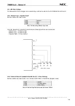
2.2.2 SW2
SW2 can set the input voltage for A/D converter (ANI
1
).
SW1
Mode
TEMP
Connect the output of temperature sensor to A/D converter (ANI
1
terminal)
Ext Volt
Connect the voltage of J5 connector to A/D converter (ANI
1
terminal)
Table 3: SW2 modes
2.2.3 SW3
SW3 can select if it uses microcontroller built-in operational amplifier 0 or not.
SW3
Op-Amp 0
Remarks
ON
Use
Amplify 10-fold the voltage input to J5 connector by using operational
amplifier 0.
* Set SW2 to "Ext Volt" side.
OFF
Not Use
Not to use operational amplifier 0
Table 4: SW3 modes
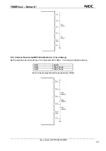
2.2.4 SW4 (Cursor)
SW4 is 4 Ways + Center-push Switch. It becomes "Low" when it is pushed or shifted to the side. It becomes
"Open" when it is released. You need to set microcontroller built-in pull-up option resistor (PU7) to "ON". (For
details about settings of microcontroller built-in pull-up option resistor, refer to the
78K0R/Lx3).
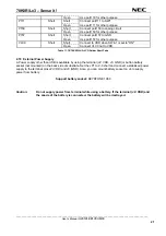
SW 4
Target Microcontroller Pin Name
Remarks
1pin
P70/KR0
UP
2pin
P71/KR1
CENTER PUSH
3pin
P72/KR2
LEFT
4pin
P74/KR3
RIGHT
5pin GND
6pin
P73/KR3
DOWN
Table 5: SW4 modes
2.2.5 SW5
SW5 can select the time-sharing of LCD.
SW5
Time-Sharing
ALL OFF
4, 3, 2, Static
ALL ON
8


