background image

4. MAIN FEATURES 

N-BUS device energy parameter monitoring: State of 

Charge (SoC) of Tempra battery, Solar Energy, DC-DC 

charge when vehicle is in motion. 

Accurate, real-time consumption monitoring. 

Control of all N-BUS devices to activate or deactivate 

a  device,  choose  charge  curve,  select  settings  in 

general. 

Voltage and ampere charge display Date and time. 

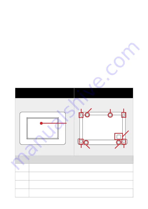
5. DISPLAY STRUCTURE 

4

FUNCTION

1

Touch screen Display

2

Communication cable hole

3

4 holes for wall fixing

4

Display cover plate to mounting frame fixing holes

DISPLAY

MOUNTING FRAME

1

4

2

3

3

3

4

4

4

3

Содержание DTB01

Страница 1: ...1 DISPLAY BUS User Manual ENGLISH VALID FOR THE MODEL DTB01 ...

Страница 2: ...he European Directive 2012 19 EU Comply with local waste disposal regulations do not dispose of old products with normal household waste The proper disposal of products that can no longer be used prevents potential negative consequences for the environment and for the population ...

Страница 3: ... MAIN FEATURES 4 5 DISPLAY STRUCTURE 4 6 INSTALLAZIONE 5 7 SETUP INIZIALE 6 8 SCREEN STRUCTURE 11 9 CUSTOM CHARGING CURVE 13 10 OTHER SETTINGS 15 11 BATTERIES 17 12 BATTERY CHARGERS DC DC 18 13 SOLAR REGULATORS AND SOLAR PANELS 19 12 TECHNICAL FEATURES 20 12 WARRANTY 22 ...

Страница 4: ... with water splashes various liquids or exposed to rain To avoid risk of electric shock and or fire the vehicle s fuel system must be in good condition In case of damaged connecting cables or inadequate section immediately replace them with suitable cables as specified by this manual or by a qualified electrician In case of anomalies in the conformity of the product do not use it it is strictly fo...

Страница 5: ...mmunication protocol Connect N BUS devices to each other with the data cable connect the DTB01 Display Bus to the network and you have the full power of the NDS power system at your fingertips With the DTB01 you can control all N BUS equipped devices such as Tempra Lithium Battery Power Service PSB DC DC Suncontrol2 SCE In addition to the DTB01 display you can also use the App for iOS and Android ...

Страница 6: ...on monitoring Control of all N BUS devices to activate or deactivate a device choose charge curve select settings in general Voltage and ampere charge display Date and time 5 DISPLAY STRUCTURE 4 N FUNCTION 1 Touch screen Display 2 Communication cable hole 3 4 holes for wall fixing 4 Display cover plate to mounting frame fixing holes DISPLAY MOUNTING FRAME 1 4 2 3 3 3 4 4 4 3 ...

Страница 7: ...ng the screws provided be sure that they do not protrude once screwed in 4 Pass the communication cable white connector through the hole previously made and insert it gently onto the display board 5 CAUTION Do not force the connector into the housing the right direction is unique a Slide the display cover plate upwards in relation to the rear mounting frame b Lift up the lower part of the display ...

Страница 8: ...s and displays the setup menus of all devices e g Suncontrol2 SCE Lithium Battery Tempra in succession Follow the steps below to best set up your N BUS network using the DTB01 Display 1 Connect the DTB01 display to an N BUS device 6 a Insert the display cover plate fixing tabs into the appropriate housing of the mounting frame b Lower the bottom side of the display cover plate by making it stick t...

Страница 9: ...seconds of the side button switches off the display and all connected N BUS devices 3 After the start up screen set the required data by moving through the various screens with the selection buttons As shown in the figures below Setup can also be completed later 7 NOTE When starting the DTB01 only the setting menus for the connected devices are shown in succession ...

Страница 10: ...ss the red button at the bottom right to go to the next screen You can skip this step and go directly to the home page by clicking on the arrow at the bottom left STEP 3 DATE Set the date by pressing the and buttons below the reference box When finished continue to the next screen by pressing the red button at the bottom right Or go back with the bottom left button ...

Страница 11: ... to the next screen by pressing the red button at the bottom right Or go back with the bottom left button STEP 6 CHARGING CURVE Set the correct charging curve in relation to the selection made in step 5 Click on the number at the side of the technology technologies not suitable according to step 5 will not be selectable The number will be highlighted in green When finished continue to the next scr...

Страница 12: ...logy and Ah will automatically be set and cannot be changed The charging curve will automatically be set to LiFePO4 No 5 STEP 7 SOLAR REGULATOR Set the power W of the connected solar panels using the plus and minus buttons on the side When finished continue to the next screen by pressing the red button at the bottom right Or go back using the bottom left button HOME SCREEN After finishing the sett...

Страница 13: ...er navigation bar Tab Bar The tab bar shows the icons of the active devices connected to the N BUS network the setting icon Settings and the return button to the Home Screen are also shown 11 Status Bar Tab Bar Device Widgets TAB BAR Solar regulator Screen Home Battery charger screen Settings Screen Batteries Inverter Screen x2 2 ...

Страница 14: ...mains presence The time alarm notifications and the display standby button are also shown The widget section varies in order and form according to the connected devices 12 STATUS BAR Bluetooth icon Notifications icon Time Display backlight off Main 220V Presence DEVICE WIDGET ...

Страница 15: ...anufacturer s requirements Follow the steps below to change the charging curve 13 STEP 1 From the home screen click on the gear symbol to enter the settings menu STEP 2 Move around the menu with the arrows at the bottom Click on the red button at the bottom right to reach screen 2 3 and click on Charging Profile ...

Страница 16: ...bsorption Vfloat Float voltage floating Vstart Starting voltage starting Select the desired options by marking the box and set the required value with the and buttons on the side then proceed to the next screen with the red button at the bottom right Float Enables the float function This function keeps the batteries always at the optimum state of charge Recondition enables the desulphation functio...

Страница 17: ...ETTINGS SCREEN 1 3 On page 1 3 of the settings m e n u y o u c a n s e l e c t settings by ticking the box e g for A c t i v a t e D e a c t i v a t e Bluetooth Activate Deactivate Silent mode silent mode for Power S e r v i c e P S B a n d SunControl2 SCE360 It is also possible to enter sub menus such as for the Display ...

Страница 18: ... the and selection buttons and finally click on the red button at the bottom right SCREEN SETTINGS 2 3 From this screen you can access sub menus to set details concerning leisure battery charging curve and solar panel power SCREEN SETTINGS 3 3 From this screen you can access sub menus to set details regarding date and time language and the list of connected N BUS devices ...

Страница 19: ... in blue is the Master i e the Master is the device that manages all others BATTERY SCREEN Clicking on the battery icon on the Tab Bar displays all data of t h e T E M P R A b a t t e r i e s connected with the N BUS I f t w o o r m o r e T E M P R A batteries are connected this screen will be displayed ...

Страница 20: ...charger or DC DC with N BUS is present in the N BUS network it will be p o s s i b l e to d i s p l a y t h e charging data of the leisure battery voltage and current and the voltage of the starter battery The charging stage the charger is in is also shown ...

Страница 21: ...S network clicking on the solar panel icon on the Tab Bar displays all data concerning the solar panels and the controller During charging the charge status of the leisure batteries is also shown By clicking on the History icon a history of the daily Ah and Wh values loaded by the SunControl2 is displayed ...

Страница 22: ...20 DISPLAY DTB01 Display Type TFT 2 83 262k full color Touch Screen Average consumption 73mA MAX brightness 33mA Display OFF 8mA during the night time Type of connection NDS Bus with 8m cable Operating temperature 10 C 70 C ...

Страница 23: ...N55014 1 2017 A11 2020 EN55014 2 2015 EN IEC 61000 3 2 2019 EN61000 3 3 2013 A1 2019 EN IEC 61000 6 1 2019 EN IEC 61000 6 2 2019 EN IEC 61000 6 3 2021 Conformity relating to the restriction of the use of certain hazardous substances is proven by compliance with the DIRECTIVE 2011 65 EU ROHS 2 EN 50581 2012 21 Commercial name DISPLAY N_BUS Models DTB01 Company NDS ENERGY S R L Address Via Giovanni ...

Страница 24: ...__________________________________________ stamp and signature of the seller model_____________________________________ SERIAL NUMBER_____________________________ Purchase date_____________________________ I CONSENT TO THE ACTIVITY DESCRIBED IN POINT 3 C OF THE INFORMATION NOTICE ON www ndsenergy it privacy policy NDS ENERGY S r l Via G Pascoli 96 98 65010 Cappelle sul Tavo PE Italy email customer...

Страница 25: ...23 ...

Страница 26: ...24 ...

Страница 27: ...25 ...

Страница 28: ...E TI SERVE ALL THE ENERGY YOU NEED 0085_MANU_DTB01_GB03 NDS ENERGY S R L Via Pascoli 169 65010 Cappelle sul Tavo Pe Italy Tel 39 085 4470396 Web www ndsenergy it Email customer ndsenergy it LIKE US facebook com ndsenergysrl ...

Отзывы: