Hardware Installation
2-39
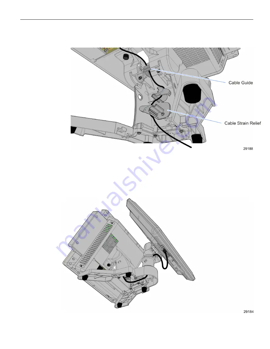
2. Route the cables through the Cable Strain Relief and over the Cable Guide as shown
below.
3. Replace the Stand Cable Cover.
Customer Display Configuration
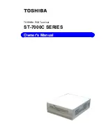
If configured with a Customer Display the cables are routed from the bottom of the
Stand up through the Customer Display Pole.
Содержание RealPOS 25
Страница 1: ...USER GUIDE NCR RealPOS 25 7610 POS Release 2 0 B005 0000 2017 Issue D...
Страница 10: ...x...
Страница 17: ...Product Overview 1 7 Note Touch Customer Displays are NOT supported via 7610 K452 and 7610 K453...
Страница 18: ...1 8 Product Overview Operator Controls Power Switch The power switch is located behind the Cable Cover...
Страница 40: ...1 30...
Страница 58: ...2 48 Hardware Installation Cable Connections Using DVI Interface...
Страница 60: ...2 50 Hardware Installation Cable Connections Using DVI Interface...
Страница 62: ...2 52 Hardware Installation Cable Connections Using DVI Interface...
Страница 63: ...Hardware Installation 2 53 Installing a 5982 6 5 Inch LCD 1 Remove the Base from the Display 2 screws...
Страница 74: ...2 64 Hardware Installation Dual Display Clone 1 Select Multiple Displays...
Страница 82: ...2 72...
Страница 94: ...3 84...
Страница 102: ...4 92...
Страница 112: ...6 102...
Страница 116: ...7 106...
Страница 121: ...2x20 Customer Display Interface 8 111 CP437...
Страница 122: ...8 112 2x20 Customer Display Interface CP852...
Страница 123: ...2x20 Customer Display Interface 8 113 CP858...
Страница 124: ...8 114 2x20 Customer Display Interface CP866...
Страница 125: ...2x20 Customer Display Interface 8 115 CP932...
Страница 126: ...8 116...
Страница 132: ...9 122...
Страница 134: ...A 2 Powered Serial Port Settings Motherboard 1 x...
Страница 135: ...Powered Serial Port Settings A 3 Motherboard 2 x...
Страница 136: ......
Страница 138: ...B 6 Display Color Adjustment Windows 7 Select Color Enhancement on a Windows 7 system...


