background image

8

Wireless Card and Antenna (Port C)

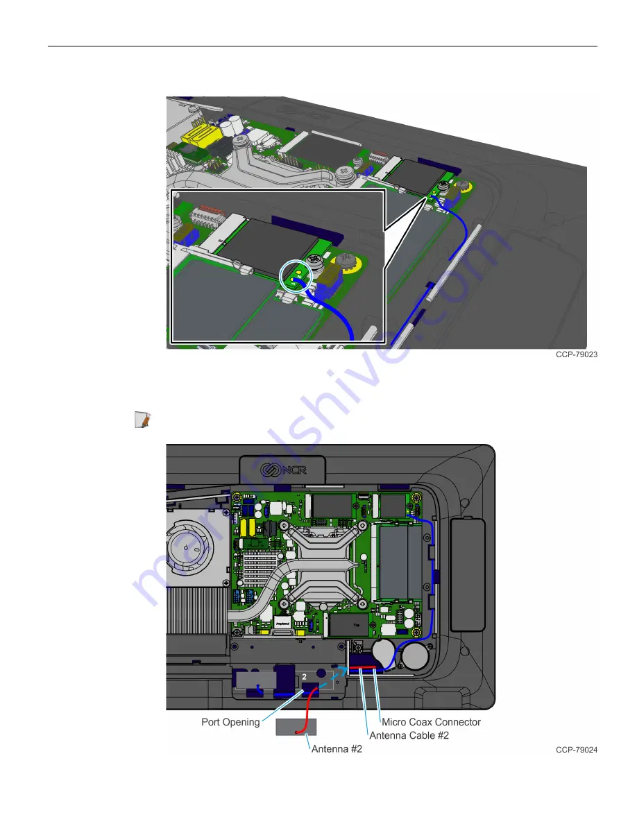
12. Connect the first Antenna Cable to Connector 1 (Aux) of the Wireless Card.

13. Route the second Antenna Cable through the port opening located as shown and

pull the Cable completely through.

Note:

If present, remove the protective cover from the Micro Coax Connector.

Содержание Port C

Страница 1: ...Kit Instructions Wireless Card and Antenna Port C 7772 K168 Issue A...

Страница 2: ...are and firmware become available NCR therefore reserves the right to change specifications without prior notice All features functions and operations described herein may not be marketed by NCR in al...

Страница 3: ...Wireless Card and Antenna Port C This kit provides a Wireless Card and Antenna for Port C of the NCR CX7 All in One POS 7772 or NCR CX5 All in One POS 7773 Kit Contents...

Страница 4: ...wn on a flat surface Note Always use a soft material cloth foam to protect the display screen when placing the terminal face down 2 Remove the Cable Cover a Remove the two 2 screws that secure the Cab...

Страница 5: ...e Cables a Loosen the thumbscrew of the 180 degree USB C Cable then disconnect the Cable b Remove the Ethernet Cable from the Cable Management Hook then disconnect the Cable 4 Loosen the two 2 captive...

Страница 6: ...4 Wireless Card and Antenna Port C 5 Rotate the Back Cover away from the Display and unhook the Back Cover Tabs...

Страница 7: ...Wireless Card and Antenna Port C 5 6 Insert a flat screw driver in the slot to unsnap the Peripheral Filler Plate from Port C of the display housing 7 Insert the Wireless Card into the connector...

Страница 8: ...a Port C 8 Secure the Card with a screw 9 Route the first Antenna Cable through the port opening located as shown and pull the Cable completely through Note If present remove the protective cover from...

Страница 9: ...ntenna and place the Antenna on the location marked 1 on the display housing Ensure the solder joint of the Antenna is within the opening 11 Route and secure the Antenna Cable under the Cable Manageme...

Страница 10: ...first Antenna Cable to Connector 1 Aux of the Wireless Card 13 Route the second Antenna Cable through the port opening located as shown and pull the Cable completely through Note If present remove th...

Страница 11: ...na and place the Antenna on the location marked 2 on the display housing Ensure the solder joint of the Antenna is within the opening 15 Route and secure the Antenna Cable under the Cable Management H...

Страница 12: ...the Wireless Card Note For clarity the first Atenna Cable is not shown in the illustration 17 Hook the Peripheral Filler Plate into the display housing and snap into place 18 Reinstall the Display Bac...

Отзывы: