background image

11 

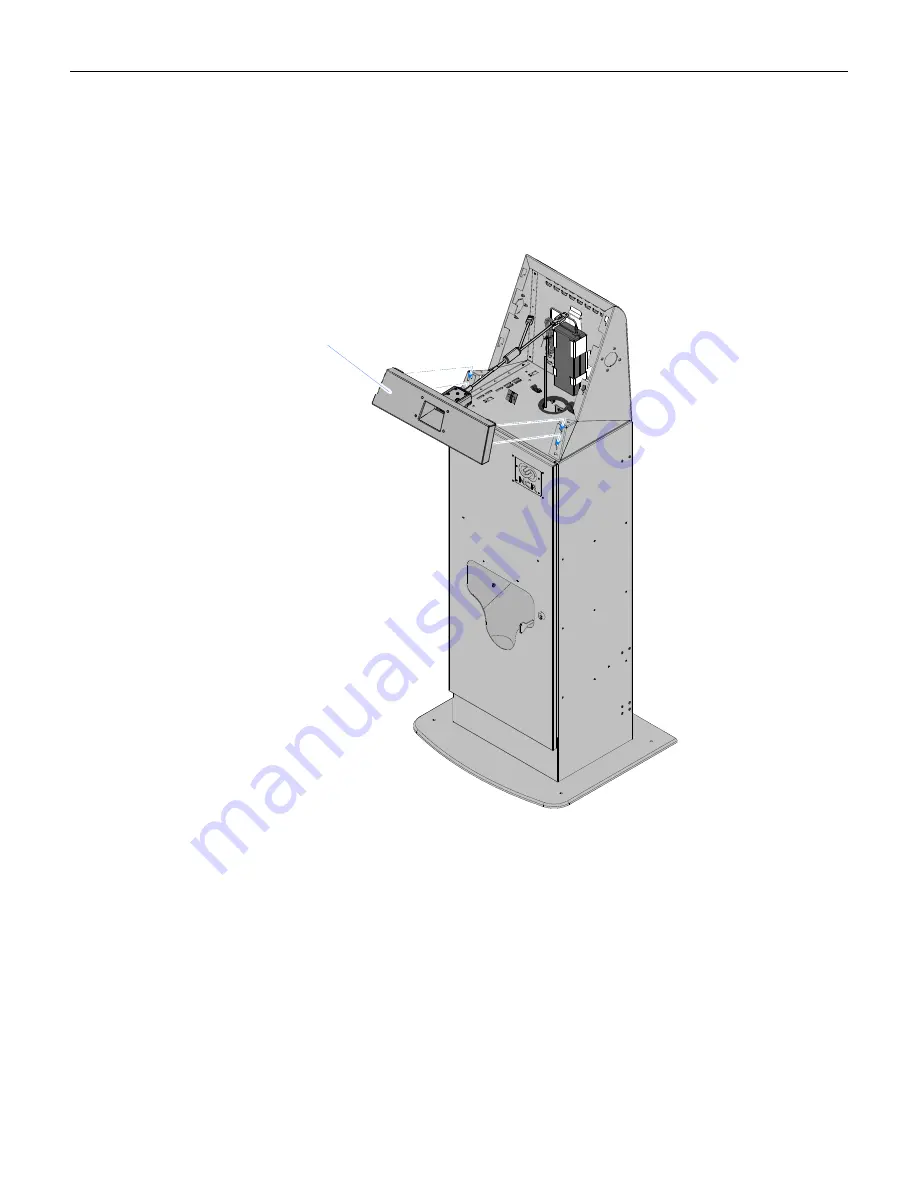
Installing the Pedestal Filler Plate with N5680 Image Scanner (7409-K078) 

1.


Connect


the


scanner


cable


to


the


scanner.


2.


Align


the


tabs


(4)


on


the


back


of


the


Filler


Plate


with


the


corresponding


slots


(4)


on


the


front


of


the


Upper


Pedestal


Cabinet.


3.


Slide


the


Filler


Plate


down


to


lock


it


into


position.


31459

Pedestal Filler Plate w/Scanner
(7409-K078)


4.


Later,


after


installing


the


terminal,


connect


the


scanner


cable


to


a


USB


port


on


the


terminal


I/O


panel


Содержание 7409 K065

Страница 1: ...7409 K065 Kiosk Full Page Printer Pedestal Kit Instructions Issue D...

Страница 2: ...Revision Record Issue Date Remarks A Nov 2009 First issue B Aug 2010 Added installation procedures for Filler Plate Keyboard options C Mar 2011 Added 7409 K076 D Sept 2012 Added new Imager kits...

Страница 3: ...and power supply The USB data cable is also included This kit is used in conjunction with the Printer Pedestal Upper Cabinet Kit 7409 K060 which supports the NCR SelfServ 60 Kiosk 7409 or the NCR Eas...

Страница 4: ...destal should be bolted to a floor Secure the base to the floor with bolts that are appropriate for the floor type Use the 16 mm 5 8 holes 4 located inside the pedestal 27745 Floor Mounting Holes 4 X...

Страница 5: ...Display Bracket Upper Cabinet 2 Install the correct Power Supply Bracket Note The 7409 Power Supply Bracket is pre installed in the Upper Cabinet If you are installing a 7404 replace the installed br...

Страница 6: ...Align the slots 4 on the bottom of the Upper Cabinet with the tabs 4 on the top of the Lower Cabinet 4 Slide the Upper Cabinet toward the rear of the unit to lock it into position 27942 Slots 4x Tabs...

Страница 7: ...re the Upper Cabinet with the thumbscrews 2 located under the top of the Lower Cabinet Note There is a third thumbscrew in the center of the cabinet that is not used on this model 27940a Not Used Thum...

Страница 8: ...6 6 Install the Grommet in the cable routing hole 27943 Grommet...

Страница 9: ...7 7 Insert the Terminal Power Supply into the bracket 27944 Terminal Power Supply...

Страница 10: ...8 8 Connect the Terminal AC Power Cord to the Power Supply Route the other end of the cord outside the pedestal see the Cable Routing section 27945 Cable Routing Hole AC Power Cord...

Страница 11: ...680 Image Scanner 7409 K078 Pedestal Keyboard Tray 7409 K063 requires Rugged Keyboard 2336 K212 Pedestal Keyboard Tray with N5680 Image Scanner 7409 K080 Pedestal Keyboard Tray w MS3207 Bar Code Scann...

Страница 12: ...Plate 7409 K061 1 Align the tabs 4 on the back of the Filler Plate with the corresponding slots 4 on the front of the Upper Pedestal Cabinet 2 Slide the Filler Plate down to lock it into position 2797...

Страница 13: ...the tabs 4 on the back of the Filler Plate with the corresponding slots 4 on the front of the Upper Pedestal Cabinet 3 Slide the Filler Plate down to lock it into position 31459 Pedestal Filler Plate...

Страница 14: ...s housing for the 2336 K212 Keyboard 1 Insert the 2336 K212 Keyboard into the bottom of the Pedestal Keyboard Housing and secure it with the Rugged Keyboard Clamps 2 and Hex Nuts 8 27980 Pedestal Keyb...

Страница 15: ...the back of the Pedestal Keyboard Housing with the corresponding slots 4 on the front of the Upper Pedestal Cabinet 3 Slide the Keyboard Assembly down to lock it into position 29459 Pedestal Keyboard...

Страница 16: ...slots 2 in the bottom of the Pedestal Keyboard Housing and Upper Cabinet 29460 Tab X2 Keyboard Bottom Cover 5 Secure the Keyboard Bottom Cover with screws 2 29461 6 Later after installing the terminal...

Страница 17: ...es housing for the 2336 K212 Keyboard and a Bar Code Scanner 1 Insert the 2336 K212 Keyboard into the bottom of the Pedestal Keyboard Housing and secure it with the Rugged Keyboard Clamps 2 and Hex Nu...

Страница 18: ...er Mount Bracket with screws 3 30348 MiniScan Scanner Scanner Mounting Bracket 3 Secure the scanner to the Bottom Keyboard Cover 2 screws 30349 Bottom Keyboard Cover 4 Connect the Scanner Cable to the...

Страница 19: ...destal Keyboard Housing with the corresponding slots 4 on the front of the Upper Pedestal Cabinet 6 With the tabs seated in the slots slide the Keyboard Assembly down to lock it into position 30351 Pe...

Страница 20: ...Keyboard Housing and Upper Cabinet 30352 Tab X2 Keyboard Bottom Cover 8 Secure the Keyboard Bottom Cover with screws 3 30353 9 Later after installing the terminal connect the scanner and keyboard cab...

Страница 21: ...Scanner 7409 K080 This kit provides housing for the 2336 K212 Keyboard and a N5680 Image Scanner 1 Remove the Keyboard Bottom Cover and Scanner Assembly from the Keyboard Housing 2 screws 31489 Keybo...

Страница 22: ...2336 K212 Keyboard into the bottom of the Pedestal Keyboard Housing and secure it with the Rugged Keyboard Clamps 2 and Hex Nuts 8 27980 Pedestal Keyboard Housing 2336 K212 Keyboard Rugged Keyboard Cl...

Страница 23: ...21 3 Align the tabs 4 on the back of the Pedestal Keyboard Housing with the corresponding slots 4 on the front of the Upper Pedestal Cabinet 4 Slide the Keyboard Assembly down to lock it into position...

Страница 24: ...Bottom Cover tabs 2 into the corresponding slots 2 in the bottom of the Pedestal Keyboard Housing and Upper Cabinet 29462 Tab X2 Keyboard Bottom Cover and Scanner Assembly 6 Secure the Keyboard Botto...

Страница 25: ...ponding slots 4 on the front of the Upper Pedestal Cabinet 2 Slide the assembly down to lock it into position 28725 Pedestal PIN Pad Dip MSR 7409 K068 3 Later after installing the terminal connect the...

Страница 26: ...n handling you can remove the 7409 Rear Cover from the Display Assembly before installing the terminal on the pedestal 1 Lay the terminal face down on a flat surface 2 Loosen the captive screws 2 that...

Страница 27: ...25 3 Pivot the Rear Cover to the open position 4 Remove the Rear cover by squeezing the Rear Cover Latches together to retract the pins as indicated below 26651 Rear Cover Latches Pins...

Страница 28: ...rds them otherwise 28743 Display Mount Side Covers 2 Install the Display Bracket onto the terminal Rear Cover 4 screws There are two sets of holes in the Display Bracket All 7409 terminals use the A s...

Страница 29: ...27 3 Align the tabs 4 on the back of the Display Bracket with the slots 4 on the Upper Cabinet 4 Slide the assembly downward to lock it into position 27947 7409 Rear Cover Display Bracket Assembly...

Страница 30: ...the Rear Cover hinge Align the hinges and squeeze the Rear Cover Latches together to retract the pins Once aligned release the latches Close the display 27948 Rear Cover Latches 5 Tighten the captive...

Страница 31: ...al 4 screws There are two sets of holes in the Display Bracket Use the A set of holes for 17 displays and the B holes for 15 displays Note The screws used are included on the Rear Cover of the termina...

Страница 32: ...Align the tabs 4 on the back of the Display Bracket with the slots 4 on the Upper Cabinet 3 Slide the display bracket assembly downward to lock it into position 27947a 7404 Display Display Bracket Ass...

Страница 33: ...options are installed 7409 27661 RS232 B RS232 A A B Line Out 2 Line Out 1 Mic Power D V I I DC In LAN C D E F USB Ports Terminal Power 7404 27660 Mic OutMic In COM4 COM3 COM2COM1 USB USB Parallel On...

Страница 34: ...32 Cable Routing Use the illustration below to connect and route the cables 27744 Terminal DC Power Terminal AC Power Terminal DC Power Printer Data USB Printer AC Power Printer DC Power...

Страница 35: ...Printer 27052 Power Connector USB Connector 3 Route the AC Power Cord up through the Cable Guide then down the Lower Cabinet as shown in the Cable Routing section earlier in this document Secure the c...

Страница 36: ...feature of the printer 2 Insert the paper roll onto the spindle 27013 Note The paper edge must unroll from the bottom as shown above 3 Place the paper roll onto the Printer Cradle 27014 Note To preven...

Страница 37: ...d of the paper into the printer The auto feed picks up the paper and cuts it to length 27015 Removing Paper from the Printer Feed Rolls If paper becomes jammed in the printer feed rolls follow the pro...

Страница 38: ...rom the hooks in the Printer Mounting Bracket 28742 Captive Screw References The NCR 2ST Full Page Printer is replaceable in the field as a complete module Field level diagnostics and setup are not ty...

Отзывы: