background image

20

5

Installing the Mounting Bracket

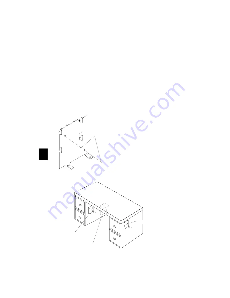
There are various places the mounting bracket may be attached. 
Examples include attaching the bracket on a wall or on your desk, as 
shown in the illustration. In determining where to attach the bracket, 
keep the following in mind: 

Are the cables you have attached to the base long enough to reach 
from the bracket to the keyboard, mouse, and monitor?

Is the fixture where you’re attaching the bracket secure enough to hold 
the bracket and base?

Is the area where you’re placing this bracket and base out of the way 
of traffic, so that the unit will not be bumped?

Is there enough clearance around the unit for cables and air 
circulation?

To mount the bracket:

1. Select the location to 

attach the bracket.

2. Use the two flathead 

screws (supplied), and 
secure the bracket to the 
fixture.
Make sure the screw 
heads are flush with the 
bracket before attaching 
the base.

Use two screws

Possible areas for mounting the bracket.

Inside of Desk

Outside of Desk

Underneath Desk Top

Содержание Explora Series

Страница 1: ...1995 Network Computing Devices 350 North Bernardo Ave Mountain View California 94043 1 2 3 4 5 6 About the Explora Family Explora Product Line Basic Installation Selecting Screen Resolution Installin...

Страница 2: ...digital apparatus set out in the Radio Interference Regulations of the Canadian Depart ment of Communications Le pr sent appareil num rique n met pas de bruits radio lectriques d passant les lim ites...

Страница 3: ...monitor support PS 2 mouse support Multiple keyboard choices Serial RS 232 C connection Parallel connection Externally accessible PCMCIA card slot Built in twisted pair and or thin Ethernet connection...

Страница 4: ...ntact NCD at 415 694 0650 or your representative immediately Note Optional equipment installation is covered in Section 5 Optional Single Power Source Attachment see Section 5 COLOR 1 3 2 N C D N C D...

Страница 5: ...making network connections Explora has only a twisted pair connector N C D N C D N C D N C D Xxx Power Switch Power Indicator Network Activity Indicator Front View Back View Twisted Pair Link Look Th...

Страница 6: ...e power supply last Caution Do not set the monitor on top of the base The base is not designed to hold a monitor Explora Mouse Keyboard Power Supply Monitor Parallel Serial Network Connection T w i s...

Страница 7: ...the following appear Press the Escape key to interrupt the booting process Searching for IP address Using IP address IP address of terminal Searching for subnet mask Using subnet mask subnet mask loa...

Страница 8: ...60Hz 640 x 480 72Hz 640 x 480 75Hz 800 x 600 60Hz 800 x 600 72Hz 800 x 600 75Hz 1024 x 768 60Hz 1024 x 768 70Hz 1024 x 768 75Hz Monitor Resolution Supported resolutions for Explora Help Keyboard Monit...

Страница 9: ...he following menu appears 12 Use the up or down arrow keys to select one of the options from the Done menu Reboot saves the settings you changed and reboots the system Exit saves the settings and retu...

Страница 10: ...er vendors Contact NCD Technical Support for information about approved vendors Only SIMMs supplied by NCD are covered under NCD s warranty Notes Explora has 4 MB of built in memory and 1 MB of built...

Страница 11: ...ing the terminal base and 4 testing the memory after your terminal is up and running If you don t feel confident performing these pro cedures on your terminal refer the unit to a qualified service cen...

Страница 12: ...e it on a flat surface so that the base top is facing up and the front is facing you 6 Grasp the tabs protruding from the back of the unit with your forefinger as shown 7 Gently pull the tabs away fro...

Страница 13: ...t the base on an anti static mat and wear a grounding strap Explora Explorapro J9 J9 J10 The SIMM socket s are located on the left side of the logic board To install the SIMM s 1 Orient the SIMM so th...

Страница 14: ...s or your thumbs pull back on the two metal tabs located on each end of the SIMM socket 2 As you pull back on the tabs the SIMM pops up past the metal tabs 3 Hold the SIMM on both ends you should alwa...

Страница 15: ...ion and push the top cover toward the back until the two tabs click through the two openings on the bottom section 3 Once the top cover and bottom section are together as a unit base turn it upside do...

Страница 16: ...re than one of these messages Press Escape each time one of them appears This aborts the load process and puts the system into the Boot Monitor prompt Memory Test Run the memory test as follows 1 At t...

Страница 17: ...ory is good 5 Add a new SIMM and rerun the memory test to confirm that the newly installed SIMM is good 6 Exit from the test and return to the Boot Monitor by typing Enter test type Q CR 7 Reset the t...

Страница 18: ...If write protect is enabled data cannot be written to the card and an error message appears if you try to do so Directional Arrow Write Protect Enable Switch set to OFF If Applicable Top of Card N C...

Страница 19: ...ng the Mounting Bracket You do not have to return to this section 1 To remove the security cover insert a medium sized flat blade screwdriver into the bottom of the slot 2 Gently pry out the security...

Страница 20: ...where you re attaching the bracket secure enough to hold the bracket and base Is the area where you re placing this bracket and base out of the way of traffic so that the unit will not be bumped Is th...

Страница 21: ...done this go back to step one in Installing the Security Device and remove the security cover 2 Attach the base to the mounting bracket using the steps above Then return here to step 3 3 Push the sma...

Страница 22: ...into the power supply block 2 Insert the power cable into the Single Power Source Attach ment connector 3 Insert the Single Power Source Attachment extension connec tor into the monitor 4 Attach the...

Страница 23: ...Transmit Data 2 Receive Data 3 Request to Send 4 Clear to Send 5 Data Set Ready 6 Signal Ground 7 Data Carrier Detect 8 Data Terminal Ready 20 Terminal DTE 9 Pin 3 Transmit Data 2 Receive Data 7 Requ...

Страница 24: ...reen Video Out 3 Blue Video Out 4 Monitor Detect 2 In 5 Ground 6 Red Video Ground 7 Green Video Ground 8 Blue Video Ground 9 No Connection 10 Ground 11 Monitor Detect 0 In 12 Monitor Detect 1 In 13 Ho...

Страница 25: ...CTIN GND Pin Signal Signal Direction 1 STROBE In 2 Data 0 In 3 Data 1 In 4 Data 2 In 5 Data 3 In 6 Data 4 In 7 Data 5 In 8 Data 6 In 9 Data 7 In 10 ACKNLG Out 11 BUSY Out 12 PE Out 13 SELECT Out 14 AU...

Страница 26: ...ibility Explorapro 2 SIMM slots expandibility NVRAM 512 Bytes both models Display memory Explora 1 MB Explorapro 2 MB Display monitor Resolution Explora 640x480 800x600 1024x768 Explorapro 640x480 800...

Страница 27: ...d N101PS 102 key international version N 102 108 key LK401 compatible keyboard N 108LK 97 key Kana keyboard Japanese charac ters N 97KAN N 123 Sun Type 5 compatible keyboard N 123 3270 Lexmark Mouse T...

Страница 28: ...he mouse cable and the base If you have problems using your mouse 1 Check the mouse cable connector Make sure it is firmly connected to the base s mouse connector 2 Turn the mouse upside down and remo...

Страница 29: ...tem for e mail To make sure that your e mail is answered quickly please follow the instructions given below Send e mail to the Internet address support ncd com or send a FAX to 415 961 7774 For both e...

Страница 30: ...ganization Title Phone number FAX number E mail address Shipping address Cut and paste the information displayed in the Console s Show Version window or provide the following information about the X t...

Страница 31: ...not pack the component yourself NCD recom mends that you take it to a commercial packing and shipping company and ask that the content be wrapped according to these instructions 4 Mark each return pa...

Страница 32: ...growing controversy over the potential health effect of VLF and ELF emissions NCD is monitoring this issue and shares the public s concern over the potential health consequences of exposure to VLF and...

Отзывы: