background image

24        Installing the System Piping

3.2    Installing a Domestic Hot Water 

(DHW) System

The Navien NCB LSWE boiler provides domestic hot water 

continuously when flow is sensed by the flow sensor. This 

method is the most efficient means of heating water by allowing 

the boiler to operate at a lower return water temperature 

by minimizing standby losses, thus increasing combustion 

efficiency. 

CAUTION


The installation must be made by sufficiently qualified 

staff, authorised to do so.


For correct installation, all the requirements and 

recommendations described in the Regulation for Heating 

Installations in Buildings (RITE) must be complied with, 

together with all other national and/or local regulations 

applicable at the time of installation.

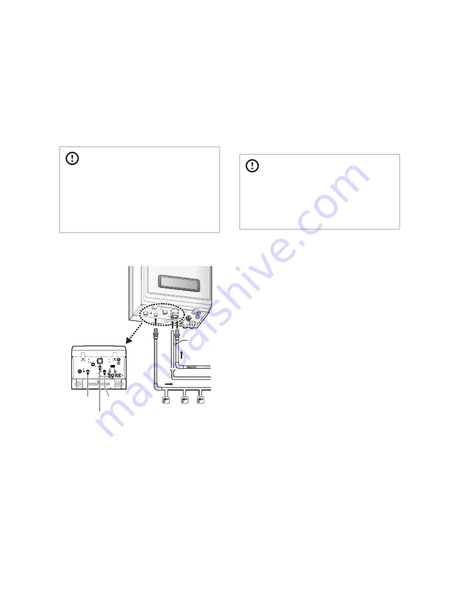
Refer to the following illustration for a typical DHW piping 

example for the boiler.

Condensate 

Drain Hose

Cold Water 

Supply

Condensate Pipe

Hot Water Supply

Bottom View

DHW Outlet 

Adaptor

Condensate 

Outlet

Water Inlet 

Adaptor

When installing the DHW system, follow these guidelines:


Use only pipes, fittings, valves, and other components (such 

as solder), that are approved for use in potable water systems.


Tighten the connection valves with care to avoid damage.


Keep the hot water piping system as short as possible, to 

deliver hot water to the fixtures more quickly.


After installing the boiler, clean the cold water inlet filter. 

Then, test the boiler for proper DHW supply and inspect for 

leaks. 

3.3    Connecting the Condensate Drain 

Line

The Navien NCB LSWE boiler creates condensation when it 

operates. This condensation has an acidic pH of 3-5. Follow 

all local codes and regulations when disposing of condensate 

from the boiler. We recommend draining the condensate into 

a laundry tub, as the alkali in laundry detergent will neutralize 

the acid in the condensate. However, other suitable waste drain 

locations may be used according to the local legislation.

CAUTION


Do not cap or plug the integrated condensate line. If 

prevented from draining, condensate can damage the 

boiler.


The condensate line must have a negative slope to drain 

properly.

The requirements recommended for the condensate drain line 

installation are as follows:


For correct condensate drain line installation, the tube must 

have a minimum diameter of Ø22 mm.


The tube must be made of a material that can withstand 

corrosion, e.g. PVC, PCV-U, ABS, PVC-C or PP. It must not be 

made of metal.


For safety reasons, the end of the tube must be as close as 

possible to the draining point.


When the condensate drainage is connected to a general 

drain network inside the building, the effects of overpressure 

that could occur inside it must be taken into account, 

installing suitable pressure release and ventilation elements.


The length of the tubes outside the building must be as short 

as possible. They must also be installed with as much tilt as 

possible. The tubes must be insulated if they are exposed 

to extremly cold weather or blizzards. If the tubes are not 

insulated, they must have a diameter of at least Ø32 mm.


The drain tube must have a minimum tilt of 2.5° downstream 

of the boiler.


For tubes with Ø22 mm, the maximum permitted length is 3 

metres.


If the appliance is installed in a non-heated premises, the tube 

system must be treated as if it was an outdoor installation.


To prevent the risk of tripping, the outdoor tubes must be 

fixed to the walls.

Before connecting the condensate drain, choose one of the 

following disposal options:

Содержание NCB-24LSWE

Страница 1: ...ice always contact an official Technical Assistance Service TAS first Contact the technician or professional who installed your boiler Contact a licensed professional for the affected system for examp...

Страница 2: ...o not store or use gasoline or other flammable vapors and liquids in the vicinity of this or any other appliance WHATTO DO IFYOU SMELL GAS Do not try to light any appliance Do not touch any electrical...

Страница 3: ...1 Flue Terminal Positions 30 5 2 Selecting a Vent System 31 5 3 Coaxial Systems 32 5 4 Dual Duct Systems 33 5 5 Measuring Vent Length 35 5 6 Terminating the Vent 35 6 Setting the DIP Switches 36 6 1 P...

Страница 4: ...bor s phone call your gas provider and follow their instructions If you cannot reach your gas provider call the fire department Do not return to your home until authorized by your gas supplier or the...

Страница 5: ...as a clothes line that could obstruct the air flow in or out of the boiler This boiler has been approved for use in the USA and Canada only Using the boiler in any other country will void the manufact...

Страница 6: ...emperature Time in which a young child can suffer a full thickness 3rd degree burn 70 C Less than 1 second 60 C 1 second 55 C 10 seconds 49 C 10 minutes 37 C very low scald risk DANGER HOT BURN To pre...

Страница 7: ...himneys UNE EN 13384 Chimneys UNE EN 13779 Ventilation UNE EN ISO 16484 Building control systems UNE EN 14336 Heating systems in buildings UNE EN 15502 1 Gas fired heating boilers Part 1 General Requi...

Страница 8: ...ded items out of the reach of children as they can be dangerous When you no longer wish to use the boiler disable any parts that could be potentially hazardous Installation Operation Manual User s Inf...

Страница 9: ...return temperature 108 6 108 4 108 4 108 3 Heat Loss through the case with burner switched on 0 1 0 1 0 1 0 1 Heat Loss through the chimney with burner switched on 1 6 1 8 1 5 1 9 Seasonal efficiency...

Страница 10: ...Equivalent elbow length at 90 60 100 m 1 3 Equivalent elbow length at 45 60 100 m 1 Max horizontal coaxial length 80 125 m 68 Max vertical coaxial length 80 125 m 70 Equivalent elbow length at 90 80...

Страница 11: ...iagram shows the key components of the boiler Component assembly diagrams and particular parts lists are included in the Appendixes Fan Motor Front Panel Flue Duct Ignitor Flame Rod Circulation Pump C...

Страница 12: ...i Mixing Chamber Air Pipe Primary Heat Exchanger Secondary Heat Exchanger Return Adapter Filter Assembly 3 way Valve Space Heating Return Pressure Relief Valve Air Vent Space Heating Supply DHW Inlet...

Страница 13: ...14 About the Boiler NCB 40LSWE Fan Motor Front Panel Flue Duct Ignitor Flame Rod Circulation Pump Condensate Trap Mounting Frame PCB...

Страница 14: ...uri Mixing Chamber Primary Heat Exchanger Secondary Heat Exchanger Return Adapter Filter Assembly 3 way Valve Space Heating Return Pressure Relief Valve Air Vent Space Heating Supply DHW Inlet DHW Out...

Страница 15: ...nections Description Diameter A Flue exhaust Air intake 60 100 80 125 B Space heating supply 22 mm C Hot water outlet DHW 15 mm D Gas supply inlet 22 mm E Cold water inlet DHW 15 mm F Space heating re...

Страница 16: ...rating Modes 1 6 1 Operating in Space Heating Mode To operate the Space heating mode press the Space heating button on the front panel and select a heating temperature setpoint higher than current hea...

Страница 17: ...t water 2 The electronic control modulates the burner output in order to constantly produce hot water at the temperature required 3 When there is no further DHW demand the burner switches off and the...

Страница 18: ...E boiler in its final location A detailed description is given of the procedure in the sequenced sections below Wall mounting Gas connection Electrical connections DIP switch settings Final check Wate...

Страница 19: ...on page 24 Adequate Drainage The boiler produces a significant amount of condensate during operation This condensate must be removed from the boiler and sutably treated if national legislation so requ...

Страница 20: ...oiler in areas where gasoline or other flammables are used or stored Ensure that combustible materials are stored away from the boiler and that hanging laundry or similar items do not obstruct access...

Страница 21: ...the tongues on the mounting bracket and hang the boiler on the bracket When mounted with the mounting bracket the boiler will have a 16 mm clearance from the back of the wall WARNING The boiler is hea...

Страница 22: ...tions and cause leaks Any dirt in the tubes could reduce boiler efficiency and cause it to malfuction Any pipes exposed to the elements or which could freeze in winter must be insulated with suitable...

Страница 23: ...when disposing of condensate from the boiler We recommend draining the condensate into a laundry tub as the alkali in laundry detergent will neutralize the acid in the condensate However other suitabl...

Страница 24: ...he 13 mmfitting at the bottom of the boiler Use only corrosion resistant material for the drain line such as PVC or CPVC Do not reduce the size of this fitting or the drain line to less than 13 mm 2 P...

Страница 25: ...at the boiler is full of water before firing the burner Operating the unit without filling it will damage the boiler Such damage is not covered by the warranty and may result in property damage severe...

Страница 26: ...following recommendations must be complied with at the least Before installing the gas pipes check the type of gas is compatible with the boiler Check that the gas meter in the home can measure the ra...

Страница 27: ...l shaded placeawayfromdirectsunlight Itmustalsobethoroughly secured to prevent it from tipping over which could cause an explosion If the boiler is used with propane a gas regulator suitable for this...

Страница 28: ...iring rate check the inlet gas pressure reading on the manometer The gas pressure must fall within the ranges specified on page 10 3 Leave the faucet on until the boiler shuts down due to a lack of ga...

Страница 29: ...m any part of the removal circuit Switch off the boiler and wait for the pipes to cool down before cleaning the gas removal and air intake ducts The gas removal and air intake ducts must be protected...

Страница 30: ...ng a Vent System WARNING The gas removal ducts must not be in contact with or near flammable materials and they must not pass through any structures or walls of buildings made of such materials If you...

Страница 31: ...m A B 500 or 1 000 851 140 min Wall Extended Removal System 80 125 Max length A B 1x90 elbow 68 2 2 65 8 m 60 100 Max length A B 1x90 elbow 20 1 3 18 7 m B A 80 125 Max length A B 1x45 elbow 68 1 67 m...

Страница 32: ...oval System 80 125 Max length A B 1x45 elbow 70 1 69 m 60 100 Max length A B 1x45 elbow 21 1 20 m A B Minimum 350 mm Pipe Diameter mm Maximum Length m Elbow Equivalent Length m 60 100 21 45 1 0 80 125...

Страница 33: ...elbow 110 2x1 4 107 2 m D C A B Minimum 370 mm Pipe Diameter mm Maximum Length m Elbow Equivalent Length m 80 80 110 45 1 4 Extended Removal System 80 80 Max length A B C D E F 4x90 elbow 110 4x2 2 10...

Страница 34: ...removal terminal The total length of the tubes must not exceed the maximum value defined If the removal installation includes elbows while calculating the total length you must take into account that...

Страница 35: ...on 1 OFF 2 OFF 24 28 34 LSWE DHW MAX 1 ON 2 OFF 40LSWE DHW 2 stage MAX 24 28 34 LSWE MIN 1 OFF 2 ON 40LSWE 1 stage MIN 24 28 34 LSWE Heating MAX 1 ON 2 ON 40LSWE Heating 2 stage MAX 3 4 Capacity 24LSW...

Страница 36: ...cal safety regulations applicable at the time of installation Note The NCB LSWE boiler has an electrical protection degree of IPX5D The electrical connection must be made via a bipolar switch located...

Страница 37: ...e lid A together with the seal B 4 Insert all these elements in the cable gland and press on the lid A until the cable is sufficiently fixed in place and the unit is sealed 7 3 Connecting the Power Su...

Страница 38: ...nterface This enables our modulating range of OpenTherm room controls to be connected without any further modifications NCB LSWE OpenTherm Protocol Room Controller 1 2 3 4 5 6 7 4 Connecting the RoomT...

Страница 39: ...is changed on gas type changeover check the gas inlet pressure Check the gas circuit is hermetically sealed Check the control panel is working correctly Check it functions normally when the boiler is...

Страница 40: ...temperature read To prevent burns on page 7 carefully Water above 52 C can cause instant scalding severe burns or death To adjust the water temperature 1 Make sure that all hot water faucets are close...

Страница 41: ...oor air temperature C with optional Outdoor Temperature Sensor only 2 Press the DHW button The DHW temperature will flash 3 Press Up or Down buttons until the desired temperature appears on the displa...

Страница 42: ...s to switch between the Operation mode types 5 To exit the Operation Mode setting and return the boiler to normal operation press the Reset button 9 5 Setting the Parameters You can modify parameter s...

Страница 43: ...O button and enter your 4 digit password Use the or buttons to increase or decrease numbers and the Summer Winter button to move between digits 5 When you are finished press the ECO button 6 Press the...

Страница 44: ...ault 2 Fan Coil 60 82 C 46 5 63 5 C 3 Cast Iron Baseboard 37 5 76 5 C 30 59 C 4 Low Mass Radiant 26 5 60 C 21 46 5 C 5 High Mass Radiant 26 5 48 5 C 21 38 C 6 Radiators 48 5 76 5 C 38 59 C 7 Custom Su...

Страница 45: ...then stops for 1 minute Default 10 C Range 6 10 C Setting the Boost IntervalTime Display Description Boost interval time min The boost interval time may be set to prevent interruption in space heatin...

Страница 46: ...ime Display Description Anti fast cycling time min The anti fast cycling time is the duration that the boiler stops its space heating operation when the space heating supply or return temperatures rea...

Страница 47: ...rks MIN set point 20 C 90 C Default 90 C Setting the DHW WaitTime Display Description DHW wait time min The DHW wait time is the duration that the boiler maintains the DHW supply mode after a DHW dema...

Страница 48: ...s menu may be used to set the burning acceleration time Default 3 min Range 0 20 min Setting the Supply Absolute MINTemperature Display Description Supply absolute Min set point C This menu can be use...

Страница 49: ...er If an error message appears reset the boiler to resolve the problem To reset the boiler press the Reset button If resetting the boiler does not solve the problem refer to the Troubleshooting sectio...

Страница 50: ...is responsible for the connection utilization repair or servicing of gas utilization equipment or accessories who is experienced in such work familiar with all precautions required and has complied wi...

Страница 51: ...8 With the internal components exposed locate the gas inlet pipe and the gas valve in the middle of the unit as shown in Figure 2 1 and Figure 2 2 Gas Valve Gas Inlet Pipe Figure 2 1 NCB 24 28 34LSWE...

Страница 52: ...here Location A Loosen the hex nut here Figure 3 2 Detaching Gas Inlet Pipe from Gas Valve and Fan Motor Assembly NCB 40LSWE Once the Gas Orifice is exposed remove the two screws that hold the part in...

Страница 53: ...5 1 Inspect the O ring between the venturi and gas valve inlet adapter whenever they are disassembled The O ring must be in good condition and must be installed Failure to comply will cause a gas leak...

Страница 54: ...ply gas type Failure to properly set the DIP switches could cause carbon monoxide poisoning resulting in severe personal injury or death 14 Turn on the gas and water supply to the boiler 15 Measure an...

Страница 55: ...match Table 2 at high fire do not adjust the gas valve Check for the proper Gas Orifice DANGER Improper gas valve settings can cause severe personal injury death or substantial property damage Option...

Страница 56: ...nal components c Fully open a hot water fixture and set the boiler to operate at 1 stage MIN mode refer to table 2 Measure the offset value at low fire and compare it to the values in Table 3 If the o...

Страница 57: ...lips screwdriver to remove the two screws four screws for NCB 40LSWE where gas inlet pipe is attached to the fan motor assembly Loosen the hex nut located above the gas vlave and remove the gas pipe R...

Страница 58: ...e boiler are safe from water Navien recommends to use a hose If the water pressure of the hose is too high water may splash to other electric parts of the boiler Keep the water pressure of the hose as...

Страница 59: ...60 Appendixes 10 3 Wiring Diagram 0 9...

Страница 60: ...Appendixes 61 10 4 Ladder Diagram...

Страница 61: ...temperature Best location to install the temperature sensor is on a North or Northeast side of a structure under eaves where the sensor is shielded from direct sunlight Avoid placing sensor in close p...

Страница 62: ...o c c a n i d e l l a t s n i n e e b s a h n i a r d e t a s n e d n o c e h T ALL INSTALLATIONS O C g n i w o l l o f e h t d r o c e r r e r u t c a f u n a m e h t y b d e r i u q e r f I 2 OR CO...

Страница 63: ...RVICE 7 Date Energy Efficiency Checklist completed Yes No Engineer Name Company Name Telephone Number Gas Safe Register Number Comments Signature SERVICE 9 Date Energy Efficiency Checklist completed Y...

Отзывы: