background image

7

1.3  Compatible Products & Pump 

Requirements

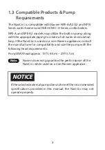
The NaviCirc is compatible with Navien NPE-A/A2/S2 and NPN 

Series water heaters and NCB-H/NFC-H Series combi boilers.
NPE-A and NPE-A2 models may utilize the built-in pump along 

with the appropriate piping to create a hot water recirculation 

loop. If the NaviCirc is used on a non-Navien appliance, consult 

the manufacturer for compatibility and size the pump with the 

following head requirements:
Pump MAX head approx. 15 ft (4.6 m) – 23 ft (7 m)

Note

Navien does not guarantee the performance of the 

NaviCirc when used on a non-Navien appliance. 

NOTICE

If the selected external pump does not meet the recommended 

specifications provided in this manual, the NaviCirc may not 

operate properly.

Содержание NaviCirc

Страница 1: ...d NCB H NFC H Series combi boilers WARNING All installations should be done only by a qualified expert and in accordance with the provided instructions by the manufacturer Before starting the installa...

Страница 2: ...tings provided in the instructions and on the product to make sure the product is suitable for the application Installers must be trained experienced and licensed service technicians Follow local code...

Страница 3: ...g the NaviCirc 11 1 6 2 Leak Check Air Purge 12 1 7 Securing the NaviCirc to the Wall 13 2 Application System 14 2 1 NPE A System 14 2 1 1 Application Guidelines 14 2 1 2 NPE A System Diagram 18 2 2 N...

Страница 4: ...4 2 4 2 Setting External Recirculation 56 2 4 3 Examples of Electrical Connections 57 2 4 4 External Recirculation with NaviCirc 62 2 4 5 External Recirculation with HotButton Optional and NaviCirc 65...

Страница 5: ...er lines by circulating hot and cold water through the NaviCirc This prevents hot water loss and heating time loss To prevent too much hot water from flowing into the cold water line the NaviCirc incl...

Страница 6: ...1 06 GPM 2 0 4 0 LPM Crossover Shutoff Temperature 95 35 Water Temperature Range 41 to 180 5 to 82 Ambient Temperature Range 32 122 0 50 Indoor use only Storage Temperature Range 14 122 10 50 Max Wat...

Страница 7: ...e a hot water recirculation loop If the NaviCirc is used on a non Navien appliance consult the manufacturer for compatibility and size the pump with the following head requirements Pump MAX head appro...

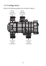
Страница 8: ...8 1 4 Configuration Refer to the following diagram for the NaviCirc layout Faucet hot water connection Hot water inlet connection Cold water inlet connection Faucet cold water connection...

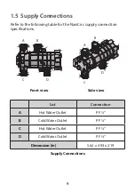
Страница 9: ...able for the NaviCirc supply connection specifications A C D B A C D B Front view Side view List Connection A Hot Water Outlet PF B Cold Water Outlet PF C Hot Water Outlet PF D Cold Water Outlet PF Di...

Страница 10: ...e instructions to install the NaviCirc to desired faucet location Use existing hoses 3 8 x 3 8 or 1 2 x 1 2 Navien flexible hoses supplied with kit only 1 2 x 3 8 3 8 to 1 2 adaptor 3 8 to 1 2 adapter...

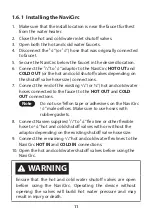
Страница 11: ...ld water hoses connected to the faucet to the HOT OUT and COLD OUT connections Note Do not use Teflon tape or adhesives on the NaviCirc 1 2 male orifices Make sure to use hoses with rubber gaskets 8 C...

Страница 12: ...e hoses to the NaviCirc Note In case of leaks close the shutoff valves and repair any leaks 5 Purge the air from the system by opening the hot water and cold water faucet Note Perform an air purge so...

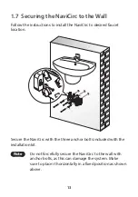
Страница 13: ...rc to desired faucet location Secure the NaviCirc with the three anchor bolts included with the installation kit Note Do not forcefully secure the NaviCirc to the wall with anchor bolts as this can da...

Страница 14: ...or EXTERNAL recirculation 1 2 3 1 2 4 5 6 7 8 9 10 ON ON 1 OFF 2 ON 2 On the front panel press the Power button to turn off the water heater 3 Enter the R D information menu by pressing the Up button...

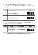
Страница 15: ...the Information button No Mode Display 1 Technical information 2 Parameter information 5 Use the Up and Down buttons to enter Parameter 17 P 17 Enable Thermal Bypass Valve Item Name Description Displa...

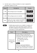
Страница 16: ...are available to adjust unit operation for various plumbing systems Refer to the NPE Installation Operation Manual for more information on these parameters Items Description Pump Cycle Interval Time P...

Страница 17: ...of time that the circulator will operate periodically in order to check the temperature of the recirculation return line and see if it needs to be re heated Setting range 1 to 120 in 1 minute incremen...

Страница 18: ...d Valve Ball Valve Ball Valve Ball Valve City water supply 1 2 3 4 ON SW1 CE1 RA1 U1 CE1 C1 C2 C7 R6 SW1 Q1 12 V SIGNAL SIGNAL 1 GND 5 V J1 R5 J2 C4 ZD1 R7 D1 CON3 CON2 CON1 SIGNAL SIGNAL 3 GND SIGNAL...

Страница 19: ...e end user might experience lukewarm water when first opening the cold water tap Maximum recirculation pipe lengths 100 feet approx 30 m equivalent length of copper pipe 400 feet approx 120 m equivale...

Страница 20: ...ation of the wiring 2 Remove the front cover from the unit and remove the PCB by removing the 2 attaching screws from the housing 3 Use a 120 VAC max 1 5 A normally closed solenoid valve for this appl...

Страница 21: ...attach the external pump wire and solenoid valve assembly to this connector TB1 7 Locate the 10 switch set of dipswitches on the front panel and verify that DIP SW2 is ON for EXTERNAL recirculation 1...

Страница 22: ...ulation mode and DIP switch settings refer to the NPE A2 S2 Installation Manual 2 2 1 Setting External Recirculation Mode To use the external recirculation mode 1 Connect the water supply to support r...

Страница 23: ...23 3 Press the Menu button to access the Main menu and select 1 Recirculation Setting 2 External Recirculation by pressing the OK button...

Страница 24: ...re Connection on page 26 first and select YES on the screen asking whether the external pump is connected to the PCB Model Step 1 Step 2 Step 3 A2 type Ext Recirc Use Ext Pump Yes No Always On Intelli...

Страница 25: ...ating External Recirculation Mode using the Recirculation Inlet Primary Heat Exchanger Secondary Heat Exchanger Buffer Tank Flow Sensor Domestic Water Supply Hot Water Supply Recirculation Water Suppl...

Страница 26: ...prevent death or serious injury or property damage DO NOT remove the front cover unless the power to the water heater is turned off or disconnected ALWAYS check the water heater is turned off before...

Страница 27: ...move the water heater front cover by loosening the 4 Phillips head screws securing it to the case 2 Locate the power switch on the right side of the front panel and switch the system off Turn the swit...

Страница 28: ...x in place and remove the PCB box from the system Remove Screws here 4 Connect the external pump wiring connector to the connector socket on the PCB TB1 TB1 5 Put the PCB box back in its original plac...

Страница 29: ...connecting it to the pump 7 Connect the external pump wire to the proper wires from the pump junction box WARNING ONLY turn on the water heater after connecting the wire to the external pump to preve...

Страница 30: ...can configure it as either Type 1 or Type 2 if you install an external recirculation line C H G Condensate Gas Domestic Cold Water Domestic Hot Water Domestic Recirculation Return Type 1 Recirculatio...

Страница 31: ...31 C H G Condensate Gas Domestic Cold Water Domestic Hot Water Domestic Recirculation Return Type 2 Recirculation Using a Second Pump NPE A2 Models Navien Internal Pump External Pump...

Страница 32: ...ion functionality With the HotButton kit DHW recirculation is carried out exactly when the actual demands arise This prevents energy loss caused by unnecessary operation of the burner and pump through...

Страница 33: ...stem has been installed Device Layout Refer to the following diagram for the product layout CE1 CE2 U1 C1 C2 C7 R6 PC1 12 V 5 V SIGNAL SIGNAL 1 GND R5 R9 R8 C3 R1 R2 R7 D1 CON3 CON5 CON2 CON1 SIGNAL 2...

Страница 34: ...nsor connection Connecting Wired Switches Refer to the following diagrams to connect a wired switch or multiple wired switches to the HotButton controller CE1 CE2 U1 C1 C2 C7 R6 PC1 12 V 5 V SIGNAL SI...

Страница 35: ...itch to the branch 1 2 3 4 ON SW1 CE1 CE2 U1 C1 C2 C7 R6 PC1 12 V 5 V SIGNAL SIGNAL 1 GND R5 R9 R8 C3 R1 R2 R7 D1 CON3 CON5 CON2 CON1 SIGNAL 2 SENSOR I RA1 Multipleswitchesconnecteddirectlytothesamete...

Страница 36: ...6 and wall plates GXXX001427 can be purchased through Navien HotButton DIP Switch Information CE1 CE2 U1 C1 C2 C7 R6 PC1 12 V 5 V SIGNAL SIGNAL 1 GND R5 R9 R8 C3 R1 R2 R7 D1 CON3 CON5 CON2 CON1 SIGNAL...

Страница 37: ...culation system s basic operation of an NPE A2 S2 series water heater system with the Navien NaviCirc and Navien HotButton kit with or without a dedicated return line Note The NPE A2 S2 series water h...

Страница 38: ...ply Expansion Tank DHW Supply Ball Valve Wired Push Button 1 2 3 4 ON SW1 CE1 CE2 U1 C1 C2 C7 R6 PC1 12 V 5 V SIGNAL SIGNAL 1 GND R5 R9 R8 C3 R1 R2 R7 D1 CON3 CON5 CON2 CON1 SIGNAL 2 SENSOR I RA1 NPE...

Страница 39: ...39 Return Water Flexible Hoses Flexible Hoses NaviCirc Temperature Sensor Wired Push Button Wired Push Button...

Страница 40: ...al Pump NPE S2 Water Heater City Water Supply Expansion Tank DHW Supply Wired Push Button 1 2 3 4 ON SW1 CE1 CE2 U1 C1 C2 C7 R6 PC1 12 V 5 V SIGNAL SIGNAL 1 GND R5 R9 R8 C3 R1 R2 R7 D1 CON3 CON5 CON2...

Страница 41: ...41 Return Water NaviCirc Temperature Sensor Wired Push Button Wired Push Button...

Страница 42: ...ized to maintain a flow of 2 4 GPM through the water heater Follow the instructions below when connecting the pump wire accessory to the PCB WARNING Electric shock hazard To prevent death or serious i...

Страница 43: ...ments than the listed specification above a relay should be used to ensure proper operation 1 Disconnect the power supply to the water heater 2 Remove the two upper screws from the front cover assembl...

Страница 44: ...x in place and remove the PCB box from the system Remove Screws here 4 Connect the external pump wiring connector to the connector socket on the PCB TB1 TB1 5 Put the PCB box back in its original plac...

Страница 45: ...a wire stripper before connecting it to the pump 7 Connect the External Pump Wire to the proper wires from the pump junction box WARNING ONLY turn on the water heater after connecting the wire to the...

Страница 46: ...on the front panel and turn on the proper switches based on the desired recirculation setting see Recirculation Dipswitch Settings below 1 2 3 1 2 4 5 6 7 8 9 10 ON ON NPN 160U 180U 199U 1 2 3 4 5 6 7...

Страница 47: ...he switch beside the front panel 10 Put the water heater cover back on and secure it with the 4 screws Gas Domestic Cold Water Domestic Hot Water Domestic Recirculation Return Recirculation Using Exte...

Страница 48: ...Power button to turn off the water heater 2 Enter the R D information menu by pressing the Up button three times the Down button three times and then the Up button four more times 3 In the R D inform...

Страница 49: ...Description Display 12 P12 Pump Cycle Interval Set the maximum time for pump operation or on demand operation 14 P14 Pump Sampling Time Set the pump cycle ON interval 15 P15 Differential OFF Temp Set...

Страница 50: ...ter recirculation system with the NaviCirc Note Install the NaviCirc to the faucet farthest from the water heater If installed in close proximity to the water heater faucet pipes far away may not be p...

Страница 51: ...external pump connector is not included with the water heater but it is available for purchase For more information about connecting the external pump to the water heater refer to 2 5 1 External Pump...

Страница 52: ...E1 CE2 U1 C1 C2 C7 R6 PC1 12 V 5 V SIGNAL SIGNAL 1 GND R5 R9 R8 C3 R1 R2 R7 D1 CON3 CON5 CON2 CON1 SIGNAL 2 SENSOR I RA1 Check Valve Expansion Tank City Water Supply DHW Supply Push button contact sig...

Страница 53: ...e not included with the water heater but they are available for purchase For more information about connecting the external pump to the water heater refer to 2 5 1 External Pump Wire Connection on pag...

Страница 54: ...ation press the Menu button and then select 3 DHW Operation Rotate the Command dial to switch between the list items or to increase decrease setting values Press the Command dial to select an item or...

Страница 55: ...irculation Combi Pre Heat External Note External recirculation cannot be used for cascade systems Recirculation type settings Combi Pre heat External Set to Combi Pre heat Default Always On Always On...

Страница 56: ...HW Recirculation on a weekly basis 1 1 Day schedule a command for the week 2 3 Day schedule commands for Weekdays Saturdays and Sundays 3 7 Day schedule commands for each day of the week 4 Aquastat Se...

Страница 57: ...trical components ALWAYS label all wires before disconnecting them when you work on the controls Wiring errors can cause improper and dangerous operation ALWAYS verify proper operation after servicing...

Страница 58: ...ected from the electrical supply before carrying out any servicing inside the boiler and particularly on the electric terminal strips To access the PCB carefully follow the steps below 1 Turn off the...

Страница 59: ...NC ZONE_V V3 COM NO NC ZONE_V V2 COM NO NC ZONE_V V1 Neutral Line Line LWCO LWCO Note The boiler supplies 24 VAC at the LWCO power terminals CNC3 For terminal type LWCO appliances a typical wiring me...

Страница 60: ...NE_V V3 COM NO NC ZONE_V V2 COM NO NC ZONE_V V1 SUPPLY TEMPERATU RETU N A H DHW PRI L N L N L N L N L Z3 Z2 Z1 Zone pump 1 max 2 5 A Zone pump 2 max 2 5 A Zone pump 3 max 2 5 A Pump Ground Neutral Neu...

Страница 61: ...at 1 PLY TEMPERATURE SENSOR RETURN OUTDOOR T S_ZONE3 R W C T S_ZONE2 R W C T S_ZONE1 R W C Thermostat 3 Thermostat 2 Thermostat 1 Note If you have a 24 V thermostat connect it to the R C terminals on...

Страница 62: ...est performance select the Intelligent or Weekly option in the External recirculation DHW recirculation menu To use the aquastat mode install an aquastat to the DHW pipe line and connect to the CNC6 t...

Страница 63: ...V V3 COM NO NC ZONE_V V2 COM NO NC ZONE_V V1 N A H DHW PRI L N L N L N L N L Z3 Z2 Z1 N A H DHW PRI L N L N L N L N L Z3 Z2 Z1 SUPPLY TEMPERATURE SENSOR RETURN OUTDOOR T S_ZONE3 R W C T S_ZONE2 R W C...

Страница 64: ...n pipe lengths including fittings 3 4 pipe is recommended Lengths in excess of these limits will require a larger recirculation pump Maximum Pipe Lengths Pipe Diameter 1 2 3 4 Maximum Pipe Length 100...

Страница 65: ...l recirculation DHW recirculation mode Note Combi pre heat is the default mode for DHW recirculation To select external recirculation refer to the combi pre heat and external recirculation sections in...

Страница 66: ...R RETURN OUTDOOR T S_ZONE3 R W C T S_ZONE R W Recirculation Pump Return Water City Water Supply Expansion Tank Check Valve Recirculation Pump max 2 5 A Neutral N Line L N A H DHW PRI L N L N L N L N L...

Страница 67: ...C AC24VN AC24VL lLWCO R W C T S_Recir COM NO NC ZONE_V V3 COM SUPPLY TEMPERATURE SENSOR RETURN OUTDOOR T S_ZONE3 R W C T S_ZONE2 R W C T S_ZONE1 R W C AC24VN AC24VL lLWCO R W C T S_Recir COM NO NC ZO...

Страница 68: ...3 4 pipe is recommended Lengths in excess of these limits will require a larger recirculation pump Maximum Pipe Lengths Pipe Diameter 1 2 3 4 Maximum Pipe Length 100 ft 30 m 400 ft 120 m Note To use...

Страница 69: ...ation press the Menu button and then select 3 DHW Operation Rotate the Command dial to switch between the list items or to increase decrease setting values Press the Command dial to select an item or...

Страница 70: ...irculation Combi Pre Heat External Note External recirculation cannot be used for cascade systems Recirculation type settings Combi Pre heat External Set to Combi Pre heat Default Always On Always On...

Страница 71: ...mands for DHW Recirculation on a weekly basis 1 1 Day schedule a command for the week 2 3 Day schedule commands for Weekdays Saturdays and Sundays 3 7 Day schedule commands for each day of the week 4...

Страница 72: ...trical components ALWAYS label all wires before disconnecting them when you work on the controls Wiring errors can cause improper and dangerous operation ALWAYS verify proper operation after servicing...

Страница 73: ...ected from the electrical supply before carrying out any servicing inside the boiler and particularly on the electric terminal strips To access the PCB carefully follow the steps below 1 Turn off the...

Страница 74: ...CO T S_ZONE3 W C T S_ZONE2 R W C T S_ZONE1 R W C AC24VN AC24VL lLWCO R W C T S_Recir COM NO NC ZONE_V V3 COM NO NC ZONE_V V2 COM NO NC ZONE_V V1 Neutral Live Live LWCO LWCO Note The boiler supplies 24...

Страница 75: ...ircuit LWCO Terminals Neutral Jumper Live LWCO To Boiler LWCO Terminals 2 5 3 3 Wiring Diagram Zone Pump System with Recirculation NFC H boilers can use both the 3 zone heating system and the DHW reci...

Страница 76: ...1 max 2 5 A Zone pump 2 max 2 5 A Zone pump 3 max 2 5 A Recirculation pump max 2 5 A Pump Ground Neutral Neutral Neutral Neutral Live Live Live Live N A H DHW PRI L N L N L N L N L Z3 Z2 Z1 SUPPLY TE...

Страница 77: ...ostat 1 Recirculation Timer Aquastat or HotButton Push Button If the DHW recirculation menu is set to the Always On Intelligent or Weekly option no aquastat or additional HotButton is required Note Th...

Страница 78: ...NE1 R W C AC24VN AC24VL lLWCO R W C T S_Recir COM NO NC ZONE_V V3 COM NO NC ZONE_V V2 COM NO NC ZONE_V V1 Neutral Neutral Neutral Neutral Live Live Live Live N A H DHW PRI L N L N L N L N L Z3 Z2 Z1 Z...

Страница 79: ...V2 COM NO NC ZONE_V V1 24 VAC N tat 3 24 VAC N Thermostat Input 24 VAC L Thermostat 2 24 VAC N Thermostat Input 24 VAC L Thermostat 1 Recirculation Timer Aquastat or HotButton Push Button If the DHW...

Страница 80: ...Mode For best performance select the Intelligent or Weekly option in the External recirculation DHW recirculation menu To use the aquastat mode install an aquastat to the DHW pipe line and connect to...

Страница 81: ...3 COM NO NC ZONE_V V2 COM NO NC ZONE_V V1 N A H DHW PRI L N L N L N L N L Z3 Z2 Z1 N A H DHW PRI L N L N L N L N L Z3 Z2 Z1 SUPPLY TEMPERATURE SENSOR RETURN OUTDOOR T S_ZONE3 R W C T S_ZONE2 R W C T S...

Страница 82: ...n pipe lengths including fittings 3 4 pipe is recommended Lengths in excess of these limits will require a larger recirculation pump Maximum Pipe Lengths Pipe Diameter 1 2 3 4 Maximum Pipe Length 100...

Страница 83: ...performance select the manual option in the External recirculation DHW recirculation mode Note Combi pre heat is the default mode for DHW recirculation To select external recirculation refer to the co...

Страница 84: ...TEMPERATURE SENSOR RETURN OUTDOOR T S_ZONE3 R W C T S_ZONE2 R W C T S_ZONE1 R W C Recirculation Pump Pump Ground DHW Supply Return Water City Water Supply Check Valve Recirculation Pump max 2 5 A Neu...

Страница 85: ...W recirculation systems When using the external recirculation mode observe the following maximum recirculation pipe lengths including fittings 3 4 pipe is recommended Lengths in excess of these limits...

Страница 86: ...p is not operating properly The pump is working but hot water does not reach the NaviCirc NaviCirc is not installed properly The water from the hot water tap is not hot enough even when the water heat...

Страница 87: ...t Contact Navien Technical Support Adjust the water heater temperature It is normal for some hot water to bleed over to the cold line during recirculation If the hot water discharge continues to come...

Страница 88: ...t date shall be dated upon which the end user takes title to the property Note Navien does not guarantee the performance of the NaviCirc when used on a non Navien appliance Applicable Warranty Period...

Страница 89: ...avien original factory component Navien at its sole discretion may replace the product with a new or refurbished product of comparable quality and design The replacement component or product will be w...

Страница 90: ...MEMO...

Страница 91: ...MEMO...

Страница 92: ...Installation and Operation Manual Navien Inc 20 Goodyear lrvine CA 92618 TEL 1 800 519 8794 FAX 1 949 420 0430 www navieninc com...

Отзывы: