background image


11

No Name

Description

4

Wi-Fi 

LED 

status

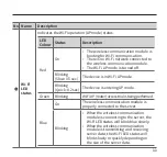
Indicates the Wi-Fi operation (AP mode) status.

LED 

Colour Status

Description

Red

On

•  The wireless communication module is 

booting for Wi-Fi communication. 

•  There is no Wi-Fi network connected to 

the wireless communication module. 

•  The Wi-Fi AP mode is turned off. 

Blinking  

(Slow: 0.5 sec) The device is in Wi-Fi AP mode.
Blinking  

(Quick: 0.2 sec) The device is entering AP mode. 

Green

Blinking

Wi-Fi AP (router) access trial is being performed.

Blue

On

The wireless communication module is 

properly connected to the server.

Blinking

•  When the wireless communication 

module is connecting to the server, the 

Wi-Fi LED status will blink blue slowly.

•  When the wireless communication 

module is transmitting and receiving 

server data, the Wi-Fi LED status will 

blink slowly or quickly depending on 

the size of the server data.

Содержание BCM-40RW

Страница 1: ...ŘŪųŦŭŦŴŴġ ńŰŮŮŶůŪŤŢŵŪŰůġ ŎŰťŶŭŦ PEFM 38 OTUBMMBUJPO 0QFSBUJPO BOVBM ...

Страница 2: ...NBSLT BOE USBEF OBNFT VTFE JO UIJT NBOVBM BSF UIF QSPQFSUZ PG UIFJS SFTQFDUJWF PXOFST G ZPVS EFWJDF SFRVJSFT TFSWJDF ZPV IBWF TFWFSBM PQUJPOT GPS HFUUJOH TFSWJDF DPOUBDU 5FDIOJDBM 4VQQPSU BU PS PO UIF XFCTJUF IUUQT OBWJFOVL DPN PS XBSSBOUZ TFSWJDF BMXBZT DPOUBDU 5FDIOJDBM 4VQQPSU GJSTU 5 EE VJMEJOH SPVOE MPPS VJMGPSE VTJOFTT 1BSL VJMEGPSE 6 9 ...

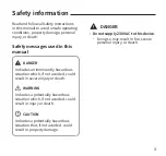
Страница 3: ...g conditions property damage personal injury or death Safety messages used in this manual DANGER Indicates an imminently hazardous situation which if not avoided could result in severe injury or death WARNING Indicates a potentially hazardous situation which if not avoided could result in injury or death CAUTION Indicates a potentially hazardous situation that if not avoided could result in proper...

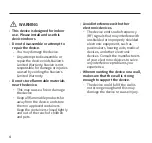
Страница 4: ...all is not strong enough and this may damage the device or cause injury WARNING This device is designed for indoor use Please install and use this device indoors Do not disassemble or attempt to repair the device _ _ You may damage the device _ _ Any attempt to disassemble or repair the device voids Navien s Limited Warranty Navien is not responsible for damage or injuries caused by voiding the Na...

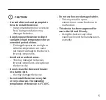
Страница 5: ...sive force during installation may damage the device Do not expose the device to direct sunlight or high temperatures for an extended period of time _ _ Prolonged exposure to sunlight or extreme temperature can cause permanent damage to the device s internal components Avoid water and wet areas _ _ This may damage the device s internal components Always keep the device dry Do not clean the device ...

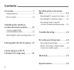
Страница 6: ...g with the RF receivers 17 Connecting to a Wi Fi network For App use 19 Resetting the connection data 21 Resetting Wi Fi connection data 21 Resetting RF connection data 21 Resetting the Wi Fi and RF connection data simultaneously 21 Troubleshooting 22 Recycling and disposal 24 Recycling the package 24 WEEE Recycling or disposing of the device and its parts 24 Warranty 25 Specifications 26 ...

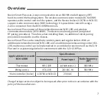
Страница 7: ...n installing them no additional initial pairing procedure is needed to use the devices Navien Smart Plus can be installed in combi system and regular boilers With an additional wireless thermostat NRC 10R and an additional wireless wiring centre VCU 10R multizone control can be implemented in a combi boiler environment via the S S Plan and in a system regular boiler environment with the S S Y W Pl...

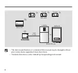
Страница 8: ... Comm Zone1 Zone2 Zone3 Or NCB CE LCB700 NRC 10R This device specifications or contents of this manual may be changed without prior notice due to upgrade of device functions The device functions can be limited by the operating environment ...

Страница 9: ...9 Supplied items Open the packaging and ensure that the following items are provided Wireless communication module Screws and anchors Wall mounting plate Extension cable Installation Operation manual ...

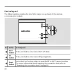
Страница 10: ...Name Description 1 Wi Fi button Press and hold to enter or exit Wi Fi AP mode 2 RF button Press and hold to enter or exit RF pairing mode 3 Reset button Insert the tip of a sharp object to reset the RF or Wi Fi connection data For more information about resetting the connection data refer to Resetting the connection data on page 21 ...

Страница 11: ...c The device is in Wi Fi AP mode Blinking Quick 0 2 sec The device is entering AP mode Green Blinking Wi Fi AP router access trial is being performed Blue On The wireless communication module is properly connected to the server Blinking When the wireless communication module is connecting to the server the Wi Fi LED status will blink blue slowly When the wireless communication module is transmitti...

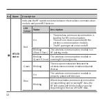
Страница 12: ...de is turned off Blinking Slow 0 5 sec The wireless communication module is in RF pairing mode Blinking Quick 0 2 sec The wireless communication module is entering RF pairing mode Green Blinking There is a poor connection between the wireless communication module and paired devices Blue On The wireless communication module is properly paired with devices Blinking When the wireless communication mo...

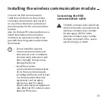
Страница 13: ...provides power for the communication module Also for the best RF system performance install the wireless communication module in an open area so that it can pair with the wiring centre and wireless thermostats Do not install the wireless communication module near heat sources such as radiators chimney walls televisions and direct sunlight Doing so may damage the device Install the wireless communi...

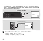
Страница 14: ...r and the end of the extension cable to one end of the KIW communication cable from the wireless communication module For NCB CE boilers For LCB700 boilers Set the DIP switches for NCB CE and LCB700 boilers as follows NCB CE Panel DIP SW 4 OFF 5 OFF LCB700 Boiler DIP SW2 6 OFF 7 ON 8 OFF ...

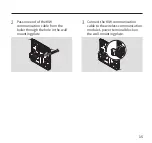
Страница 15: ... KIW communication cable to the wireless communication module s power terminal block on the wall mounting plate 2 Pass one end of the KIW communication cable from the boiler through the hole in the wall mounting plate ...

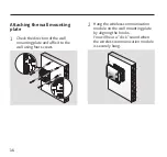
Страница 16: ... wall mounting plate by aligning the hooks You will hear a click sound when the wireless communication module is securely hung Attaching the wall mounting plate 1 Check the direction of the wall mounting plate and affix it to the wall using four screws ...

Страница 17: ... wiring centre can be paired with the wireless communication module When pairing the wireless communication module with the RF receivers such as the wiring centre or wireless thermostat the devices should be in pairing mode Refer to the Wireless thermostat or Wiring centre Installation Operation manual for information on entering pairing mode Pairing with the RF receivers ...

Страница 18: ...cannot communicate with the paired RF devices Check if the RF signal antenna icon on the wireless thermostat LCD screen appears during pairing mode 1 Turn on the power to the wireless communication module 2 Press and hold the RF button to enter pairing mode If the RF LED status blinks red slowly pairing mode is turned on To cancel or exit pairing mode press and hold the RF button 3 On the RF devic...

Страница 19: ... smartphone with the wireless communication module To connect your smartphone with the wireless communication module download and install the Navien Smart Plus app on your smartphone For more detailed information on using the app refer to the Navien Smart Plus app User Manual 1 Turn on the power to the wireless communication module 2 On your smartphone log into the Navien Smart Plus app 3 When the...

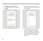
Страница 20: ...Router 2 If your smartphone has connected to the Wi Fi network successfully the wireless communication module will be connected to the selected Wi Fi and the Wi Fi LED status will turn blue 4 Tap Navien_Smart _XXXX in the Wi Fi settings to connect and then tap Next Navien_Smart _XXXX Wi Fi Navien_Smart _XXXX KD wiring centre KD thermostat ...

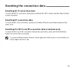
Страница 21: ...ction data press and hold the RF button and Reset button at the same time Resetting the Wi Fi and RF connection data simultaneously To reset the Wi Fi and RF connection data at the same time press and hold the Reset button for more than 10 seconds To press the Reset button located on the right side of the device insert the tip of a sharp object such as a clip Resetting the connection data ...

Страница 22: ...he wireless communication module and the paired devices _ _ Check if the wireless communication module is installed in an open area near the RF devices _ _ If the RF connection experiences interference from nearby electrical equipment or buildings choose a different installation location _ _ Check the paired RF device s pairing status _ _ Check if the devices paired with the wiring centre are oper...

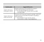
Страница 23: ...ding a poor connection _ _ Try selecting the Wi Fi network with an available connection again The Wi Fi LED status blinks blue and red There is no Wi Fi network connection available or the Wi Fi network near the communication module is providing a poor connection _ _ Check if the Wi Fi router near the wireless communication module is operating properly ...

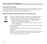
Страница 24: ...e _ _ selective collection of waste electrical and electronic equipment _ _ selective systematic treatment of certain components and substances considered to be dangerous _ _ reuse recycling and recovery of the collected waste electrical and electronic equipment Do not dispose of the device or any of its accessories with your regular household waste Ensure that the old unit and any of its accessor...

Страница 25: ...25 Manufacturer s warranty of 2 years is provided Warranty ...

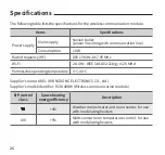
Страница 26: ... 867 95 MHz Wi Fi 2 4 GHz IEEE Std 802 11b g n 20 MHz Permissible operating temperature 0 40 Supplier s name KDEL KYUNGDONG ELECTRONICS CO Ltd Supplier s model identifier BCM 40RW Wireless communication module ErP control class Space heating energy efficiency Description VI 4 Weather compensator and room sensor for use with modulating heaters VIII 5 Multi sensor room temperature control for use with ...

Страница 27: ...UP CFDPNF UPP MPX PS IJHI PS TVCKFDUJOH UIF QSPEVDU UP BOZ BCOPSNBM PQFSBUJPO NBZ DBVTF UIF QSPEVDU T XJSFMFTT QPXFS TVQQMZ UP CFDPNF VOTUBCMF BOE JNQBDU QFSGPSNBODF 5IF QSPEVDU T TIPSU SBOHF XJSFMFTT DPNNVOJDBUJPO GVODUJPO JT DPOUSPMMFE WJB TPGUXBSF PS GJSNXBSF UP NFFU TUBOEBSET SFMBUFE UP EBUB USBOTGFS TFDVSJUZ G UIF TPGUXBSF PS GJSNXBSF JT JNQSPQFSMZ NPEJGJFE PS DIBOHFE UIF QSPEVDU T EBUB USBOT...

Страница 28: ...IUUQT OBWJFOVL DPN ...

Отзывы: