background image

BHM 

12/2/13 

NTV-Doc 112 


Agreement

End user agrees to use this product in compliance with all State and Federal laws. NAV-TV Corp. would not be held liable for 

misuse of its product.  If you do not agree, please discontinue use immediately and return product to place of purchase. This product is 

intended for off-road use and passenger entertainment only.  

1 | 

P a g e


3950 NW 120

th

 Ave, Coral Springs, FL 33065 TEL 561-955-9770 FAX 561-955-9760 

www.nav-tv.com


[email protected] 

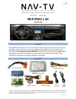
RGB PCM3.1 Kit  

(NTV-KIT420) 


Overview 

 
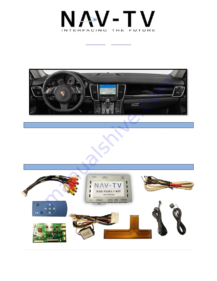
The RGB PCM3.1 kit allows the user to add up to 3 video inputs and a backup camera input to 
the factory touch screen radio in select Porsches with the PCM3.1 radio. This kit connects 
behind the radio 

following a radio modification

. The kit comes with an external toggle switch 

and if desired, forced rear camera action is an option. This manual will provide the radio 
modification procedure and vehicle installation instructions. 
 

Kit Contents 


AV Input Harness  

RGB PCM3.1 Interface 

Power Harness 

LVDS Video cable  

Remote  

Input  

Toggle  
Switch  

IR Eye  

Harness 

Sub-Board 

Ribbon T-Cable  

Содержание RGB PCM3.1 Kit

Страница 1: ...nav tv com info nav tv com RGB PCM3 1 Kit NTV KIT420 Overview The RGB PCM3 1 kit allows the user to add up to 3 video inputs and a backup camera input to the factory touch screen radio in select Pors...

Страница 2: ...and passenger entertainment only 2 P a g e Interface Connectors Dip Switch Settings Dip SW 1 2 3 4 5 6 7 8 UP Enables RGB Enables V1 Enables V2 Enables V3 N A N A Deactivates reverse cam Without fact...

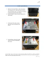
Страница 3: ...intended for off road use and passenger entertainment only 3 P a g e PCM3 1 Radio Modification 1 Remove the factory PCM3 1 radio This requires removing any vents or dash panels that hide the radio mo...

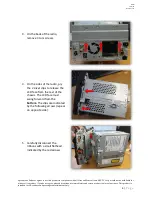
Страница 4: ...ace of purchase This product is intended for off road use and passenger entertainment only 4 P a g e 3 On the back of the radio remove 3 torx screws 4 On the sides of the radio pry the 2 silver clips...

Страница 5: ...diately and return product to place of purchase This product is intended for off road use and passenger entertainment only 5 P a g e 6 Slide the top half of the radio chassis towards the rear It may b...

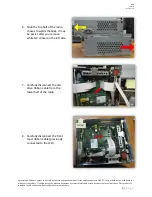
Страница 6: ...seated fully squarely and securely The end of the ribbon labeled From System BD connects to the circuit board the end labeled To LCD goes towards the LCD Run both ribbons through the access holes on t...

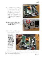
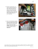
Страница 7: ...nment only 7 P a g e 12 Flip the circuit board over as it will be sandwiched between the drive and the lower half of the chassis There will be adequate clearance Run the LVDS cable through the notch y...

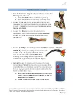
Страница 8: ...this kit 4 Connect the LVDS cable run into the radio from the modification to the interface at the port labeled LVDS OUT Connect the ground terminal to the nearest screw on the interface box 5 Connec...

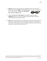
Страница 9: ...labeled MODE Pressing this switch with the ignition on will cycle the screen modes as follows factory screen NAVI RGB AV1 AV2 AV3 factory screen 8 Connect the RGB PCM3 1 Power Harness to the interface...

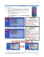
Страница 10: ...creen Use the remote OK button to switch modes or use the provided input toggle switch Hold the LEFT ARROW for 3 seconds The Menu of FACTORY will appear on screen v IMAGE MENU The only setting that ma...

Страница 11: ...or screen size Q Displayed image color is not proper too dim or color seems wrong A Try to select INITIAL in OSD menu Q Rear camera image does NOT appear A Make certain Dip Switch 7 in set down for af...

Отзывы: