BHM
12/20/16
NTV-DOC289
Agreement
:
End user agrees to use this product in compliance with all State and Federal laws. NAV-TV Corp. would not be held liable for misuse of its product.
If you do not agree, please discontinue use immediately and return product to place of purchase. This product is intended for off-road use and passenger
entertainment only.
3 |
P a g e
PCM4-VIM Installation
1.
Remove PCM4 radio. Disconnect all harnesses and set
the radio aside.
2.
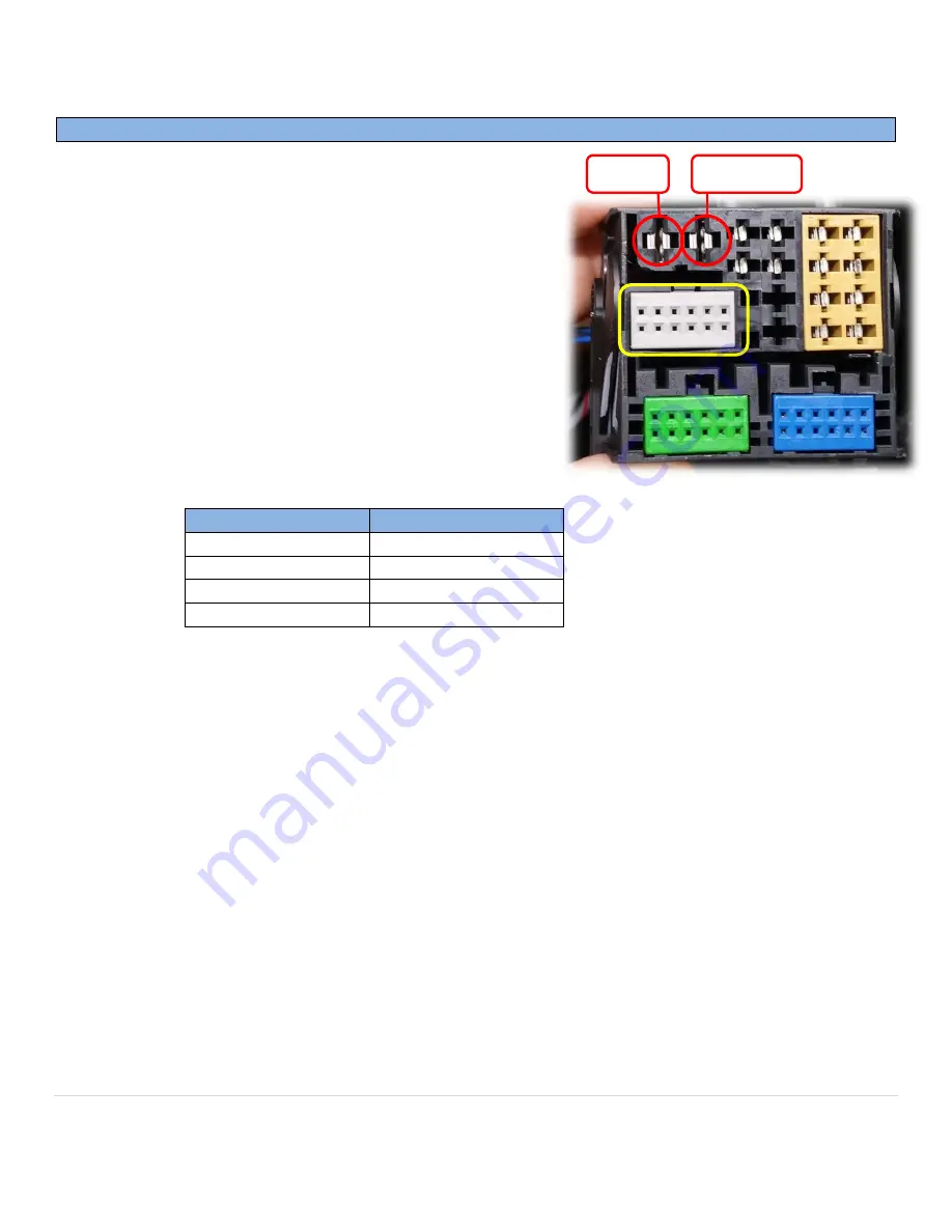
Connect the
black wire
to
ground (-)
and
yellow wire
to
constant 12v (+)
in the main radio harness. Use the
image here (right) for visual aid (test wires!).
3.
Locate the
GRAY connector
in the OEM quad-lock
connector.
This is the connector which the CAN wires
must be spliced onto (yellow square, right).
4.
On the gray connector mentioned in step 3, locate OEM
blue & blue/black twisted pair.
Cut this pair of wires in
HALF.
5.
Connect (solder) the following wires from the provided
VIM Module harness to the OEM wires:
6.
Isolate new connections to radio harness and replace radio into sub-dash.
7.
Optional (or for vehicles without SW control):
Sending INPUT 3
(12v +)
through a toggle
(not included)
will activate VIM. Otherwise, an OEM button will control VIM activation normally.
8.
Proceed to next section for PCM4-VIM functionality.
From VIM Module:
To OEM Harness:
PIN 8 (White/Blue)
Blue/Black, Radio side
PIN 9 (White/Brown)
Blue/Black, Car side
PIN 17 (Blue)
Blue, RADIO side
PIN 18 (Brown)
Blue, CAR side
12v (+)
Ground (-)


