29
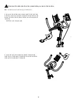
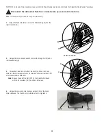
Note: Your machine may not match the image. For reference only.
.HHSWKHÀ\ZKHHOVWDEOHGXULQJWKLVSURFHGXUH
'RQRWWXUQWKHFUDQNDUPV)O\ZKHHOPRYHPHQW
FDQSXOO¿QJHUVLQDQGFDXVHLQMXU\
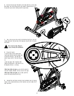
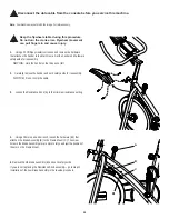
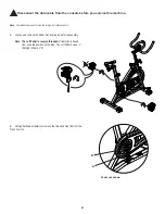
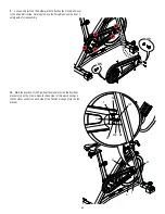
1. Using a #2 Phillips screwdriver, loosen and remove the hardware
that attaches the Fender to the Main Frame. Set the Fender and hardware
safely aside for reassembly.
NOTICE:
Hold the Fender so that it does not fall.
2. Carefully remove the Fender and set it safely aside for reassembly.
NOTICE:
Do not crimp the cable.
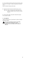
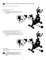
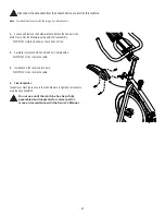
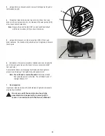
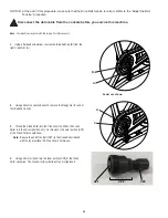
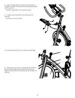
3. Loosen the Resistance Knob (A) to the minimum resistance setting.
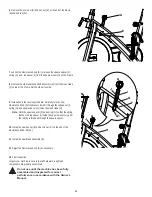
4. Using a 10mm open end wrench, loosen the hardware (B1) that
attaches the Brake Assembly (B) to the Frame Mount (C). The screw
holes in the Brake Assembly arm are slots to let you adjust the position of
the arm on the Frame Mount.
5. Remove the old Brake Assembly (B) and set it safely aside.
If you are not replacing the Resistance Knob assembly— go to step 11.
Installation of the new Brake Assembly is the reverse procedure.
Disconnect the data cable from the console before you service this machine.
A
%
%
C


