


XR12 Troubleshooting Manual
Responding to alarms
Issue 3.0 2009-07-28
Page 1-41
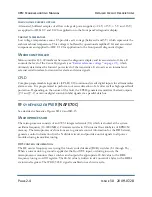
RF Drive Buffer PWB replacement
.
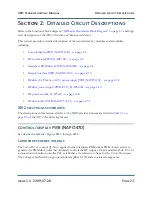
Figure 1.10: Transmitter lower front PWBs
1. Turn off the ac power at the source and wait (about 5 minutes) for the green LEDs on the
B+ distribution PWB to turn off, indicating the capacitors are discharged (see
).
2. Remove the transmitter’s lower front panel.
3. Disconnect all cables attached to the RF drive buffer PWB, taking note of the connector
labels on the cables and the PWB.
4. Remove and save six sets of mounting hardware.
WARNING:
Lethal voltages exist inside the transmitter when the power is turned
on. Turn off the power at the source and wait until the green LEDs on
the B+ distribution PWB are off before removing any connections or
RF Drive
Buffer PWB
Distribution
PWB
RF Drive
Power Supply
PWB
Содержание XR12
Страница 2: ......
Страница 4: ......
Страница 8: ...XR12 Troubleshooting Manual Table of contents Page viii Issue 3 0 2009 07 28...
Страница 12: ...XR12 Troubleshooting Manual Page xii Issue 3 0 2009 07 28...
Страница 20: ...XR12 Troubleshooting Manual Page xx Issue 3 0 2009 07 28...
Страница 100: ...XR12 Troubleshooting Manual Detailed Circuit Descriptions Page 2 32 Issue 3 0 2009 07 28...
Страница 108: ...XR12 Troubleshooting Manual Parts Lists Page 3 8 Issue 3 0 2009 07 28...
Страница 196: ......
Страница 214: ...XR12 Troubleshooting Manual Reading Electrical Schematics Page 5 6 Issue 3 0 2009 07 28...
Страница 223: ...Issue 3 1 2014 05 07 SD 9 Figure SD 9 NAPX05E 02 Dynamic Carrier Control PWB Sheet 1of 2...
Страница 224: ...Issue 3 1 2014 05 07 SD 10 Figure SD 10 NAPX05E 02 Dynamic Carrier Control PWB Sheet 2 of 2...
Страница 233: ...Issue 3 1 2014 05 07 SD 19 Figure SD 19 NAP34A RF Power Module Overall Sheet 1 of 2...
Страница 234: ...Issue 3 1 2014 05 07 SD 20 Figure SD 20 NAP34A RF Power Module Modulator Stage Sheet 2 of 2...
Страница 235: ...Issue 3 1 2014 05 07 SD 21 Figure SD 21 NAPC150A RF Drive Control PWB Sheet 1 of 3...
Страница 236: ...Issue 3 1 2014 05 07 SD 22 Figure SD 22 NAPC150A RF Drive Control PWB Sheet 2 of 3...
Страница 237: ...Issue 3 1 2014 05 07 SD 23 Figure SD 23 NAPC150A RF Drive Control PWB Sheet 3 of 3...
Страница 238: ...Issue 3 1 2014 05 07 SD 24 Figure SD 24 NASM07H Modulator Assembly...
Страница 239: ...Issue 3 1 2014 05 07 SD 25 Figure SD 25 NAA51A 03 RF Amplifier Assembly...
Страница 245: ...Issue 3 1 2014 05 07 SD 31 Figure SD 31 NAPS10C RF Drive Power Supply PWB...
Страница 248: ...Issue 3 0 2009 07 28 MD 1 Figure MD 1 XR12 Transmitter...
Страница 249: ...Issue 3 0 2009 07 28 MD 2 Figure MD 2 NAC113B Control Panel Rear View A1 Control Display PWB A2 DCC PWB optional...
Страница 251: ...Issue 3 0 2009 07 28 MD 4 Figure MD 4 NAPX05E 02 Dynamic Carrier Control PWB optional NAPX05E 01 shown NAPX05E 02...
Страница 257: ...Issue 3 0 2009 07 28 MD 10 Figure MD 10 NAPP02 01A RF Current Probe PWB...
Страница 259: ...Issue 3 0 2009 07 28 MD 12 Figure MD 12 NAFP103 05 Forward Reflected Power Probe A1 DETAIL...
Страница 263: ...Issue 3 0 2009 07 28 MD 16 Figure MD 16 NAPC150A RF Drive Control PWB...
Страница 265: ...Issue 3 0 2009 07 28 MD 18 Figure MD 18 NASM07H Modulator Assembly...
Страница 266: ...Issue 3 0 2009 07 28 MD 19 Figure MD 19 PA Input Output PWB 176 1065 04 and 05...
Страница 267: ...Issue 3 0 2009 07 28 MD 20 Figure MD 20 NAA51A 03 RF Amplifier Assembly...
Страница 268: ...Issue 3 0 2009 07 28 MD 21 Figure MD 21 NAPI47B Modulator Input Output PWB...
Страница 271: ...Issue 3 0 2009 07 28 MD 24 Figure MD 24 Relay Assy 202 7019...
Страница 272: ...Issue 3 0 2009 07 28 MD 25 Figure MD 25 Fan Tray 202 7020 J1 B1 B2...
Страница 273: ...Issue 3 0 2009 07 28 MD 26 Figure MD 26 NAPS10C RF Drive Power Supply 62 V...
Страница 275: ...Issue 3 0 2009 07 28 MD 28 Figure MD 28 Rectifier Assembly 202 7017...
Страница 282: ......