NX100 Troubleshooting Manual
Responding to alarms
Page 1-28
Issue 3.2 2016-02-08
5)3RZHU0RGXOHV
)URQW'RRU5HPRYHGIRU&ODULW\
Страница 1: ...g transmitter operation Local and or remote alarm signals are generated when a malfunction occurs If an alarm condition is caused by a malfunction in the RF power stage the transmitter may maintain op...
Страница 2: ...odular reserve IMR feature This feature permits the transmitter to operate at a reduced RF output level when a malfunction occurs in one of its power modules Station operating procedures will dictate...
Страница 3: ...ials Tools Test equipment Testing and maintenance equipment including soldering and unsoldering tools should be suitable for contact with static sensitive semiconductor devices Stress current protecti...
Страница 4: ...ame Alarm column and then by severity a single yellow indicates low severity RF output not affected a single orange indicates medium severity RF output is reduced two red indicates high severity RF ou...
Страница 5: ...ll alarms in this sub system apply to the associated rack or cabinet Module All alarms in this sub system apply to the associated RF power module Table 1 1 on page 1 6 contains a column for most Alarm...
Страница 6: ...U 3520 DLOXUH 6FKHGXOH 7KLV DODUP RFFXUV LI WKHUH LV QR YDOLG 3520 VFKHGXOH GDWD WR ORDG 5HPRYH DQG UHDSSO WKH DF SRZHU WR WKH WUDQVPLWWHU I WKH DODUP SHUVLVWV DIWHU UHSODFLQJ WKH EDWWHU UHSODFH WKH F...
Страница 7: ...SHUVLVWV DIWHU PLQXWHV UHSODFH WKH 6 RU FRQWURO LQWHUIDFH 3 VHH RQWURO LQWHUIDFH 3 UHSODFHPHQW RQ SDJH RQWUROOHU RVW 1RW 5HVSRQGLQJ 7KLV DODUP LQGLFDWHV WKDW WKH FRQWUROOHU KDV QRW UHFHLYHG DQ FRPPXQ...
Страница 8: ...WKH GLJLWDO 0 H FLWHU 3 VHH LJLWDO 0 H FLWHU 3 UHSODFHPHQW RQ SDJH RQWUROOHU 3 0 DWFK 7KLV DODUP RFFXUV LI WKH GXW F FOH RI WKH 3 0 GULYH RQ WKH DFWLYH H FLWHU LV PRUH WKDQ VWHDG VWDWH 3UHVV RF Off S...
Страница 9: ...FNHG RU DIWHU PLQXWHV LI WKH LQFRPLQJ PRGXODWLRQ OHYHO LV EHORZ 7KH SUHVHQFH RI WKLV DODUP ZLOO WULJJHU DQ H FLWHU FKDQJHRYHU LI DXWRPDWLF FKDQJHRYHU LV HQDEOHG DQG WKH WUDQVPLWWHU LV RSHUDWLQJ RQ WKH...
Страница 10: ...LEO LQGLFDWHV D IDXOW ZLWK WKH FRQWURO LQWHUIDFH 3 FOH WKH SRZHU RII WKHQ RQ WR WKH DIIHFWHG H FLWHU I WKH DODUP SHUVLVWV UHSODFH WKH DIIHFWHG GLJLWDO 0 H FLWHU 3 VHH LJLWDO 0 H FLWHU 3 UHSODFHPHQW RQ...
Страница 11: ...WKH DF PDLQV YROWDJH FRQQHFWHG WR WKH WUDQVPLWWHU DQG YHULI WKH SRZHU WUDQVIRUPHU LV WDSSHG FRUUHFWO FLWHU 0DLQ 3 8QORFNHG 7KH PDLQ FORFN VRXUFH KDV XQORFNHG 8VXDOO DFFRPSDQLHG E 1R W 0 FOH WKH SRZHU...
Страница 12: ...QG WKH ZLULQJ FRQQHFWLRQV DUH LQWDFW 9HULI WKH SRUWHU LV FRQQHFWHG WR WKH JLQH DQG WKH JLQH LV UHFHLYLQJ GDWD IURP WKH SRUWHU I WKH DODUP SHUVLVWV UHSODFH WKH DVVRFLDWHG GLJLWDO 0 H FLWHU 3 VHH LJLWDO...
Страница 13: ...RGXOH WHUQDO LVDEOH FWLYH 7KH 3 0 GULYH FDEOH LV XQSOXJJHG 5HFRQQHFW RU UHSODFH WKH 3 0 GULYH FDEOH I WKH SUREOHP SHUVLVWV UHSODFH WKH DIIHFWHG 5 SRZHU PRGXOH VHH 5HPRYLQJ DQG UHLQVWDOOLQJ 5 SRZHU PRG...
Страница 14: ...XUH RI WKH 5 SRZHU PRGXOH LV PRUH WKDQ I WKLV DODUP LV DFFRPSDQLHG E DQRWKHU DODUP WURXEOHVKRRW WKH RWKHU DODUP ILUVW I WKH DODUP RFFXUV RQ LWV RZQ VHH 7URXEOHVKRRWLQJ 5 SRZHU PRGXOHV RQ SDJH WR GHWHU...
Страница 15: ...OHG 6WDWXV WKDW LQGLFDWHV WKH 3 0 GULYH LQ WKH 5 SRZHU PRGXOH LV HQDEOHG 0RGXOH 5HVLGXDO 3 9ROWV Q XQH SHFWHG OHYHO RI 3 YROWDJH LV GHWHFWHG ZKHQ WKH PRGXODWRU RU 3 RI D VSHFLILF 5 SRZHU PRGXOH LV GLV...
Страница 16: ...QJ 5 SRZHU UHSODFH WKH UDFN LQWHUIDFH 3 VHH 5DFN QWHUIDFH 3 UHSODFHPHQW RQ SDJH 5DFN RZ VDPSOH RI WKH SRZHU WUDQVIRUPHU V VHFRQGDU YROWDJH LV PRQLWRUHG Q DODUP RFFXUV LI WKH DF LQSXW YROWDJH LV PRUH W...
Страница 17: ...RYLQJ DQG UHLQVWDOOLQJ 5 SRZHU PRGXOHV RQ SDJH I WKH DODUP IROORZV WKH PRGXOH UHSODFH WKH PRGXOH I WKH DODUP IROORZV WKH ORFDWLRQ FKHFN WKH FRQQHFWLRQV EHWZHHQ WKH PRGXOH ORFDWLRQ DQG LWV DVVRFLDWHG S...
Страница 18: ...QJH 9 WR 9 5HSODFH WKH DIIHFWHG 9 SRZHU VXSSO VHH RZ 9ROWDJH 3RZHU 6XSSO 5HSODFHPHQW RQ SDJH 5DFN 9 36 RU DXOW 7KH 9 SRZHU VXSSOLHV 8 DQG 8 DUH PRQLWRUHG Q DODUP RFFXUV LI WKH SRZHU VXSSO YROWDJH YDUL...
Страница 19: ...H 5 3RZHU 0RGXOH 6HH SDJH 3RZHU PSOLILHU 026 7 6HH SDJH 0RGXODWRU 026 7 6HH SDJH 5HPRWH QWHUIDFH 3 6HH SDJH LJLWDO 0 FLWHU 3 6HH SDJH RQWURO QWHUIDFH 3 6HH SDJH 36 6 QF 3 6HH SDJH JLQH 3 6HH SDJH 3 0...
Страница 20: ...3 If the conditions in Step 1 and Step 2 are met suspect the control interface PWB and if necessary replace it see Control interface PWB replacement on page 1 41 Controller Interlock Open A Controller...
Страница 21: ...which can help in identifying a fault and allowing you to determine whether remedial action is required now or later Identify and isolate a defective RF power module and verify the nature of the defe...
Страница 22: ...23 for further troubleshooting information If not proceed to Step 2 2 Check and if necessary replace the the fuse on the power module interface PWB for the affected RF power module Each power module...
Страница 23: ...leshoot a Rack Low AC alarm as follows 1 Measure the ac input voltage and verify the power transformer is tapped as shown in Section 4 Connecting transformer taps load wiring on page 4 1 of the NX100...
Страница 24: ...1 2 on page 1 25 should appear Click on the associated RF power module s Front Panel Inhibit icon The icon colour should change from green to red indicating the RF power module is disabled 3 After th...
Страница 25: ...oubleshooting Manual Responding to alarms Issue 3 2 2016 02 08 Page 1 25 LJXUH LVDEOLQJ QDEOLQJ DQ 5 3RZHU 0RGXOH UHHQ LQGLFDWHV HQDEOHG OLFN WR GLVDEOH ZLOO WXUQ UHG FOLFN DJDLQ WR UH HQDEOH ZLOO WXU...
Страница 26: ...screws in the RF power module s front panel 4 Connect the RJ45 cable to the front of the RF power module If you are installing the RF power module while the transmitter is on air click on the associat...
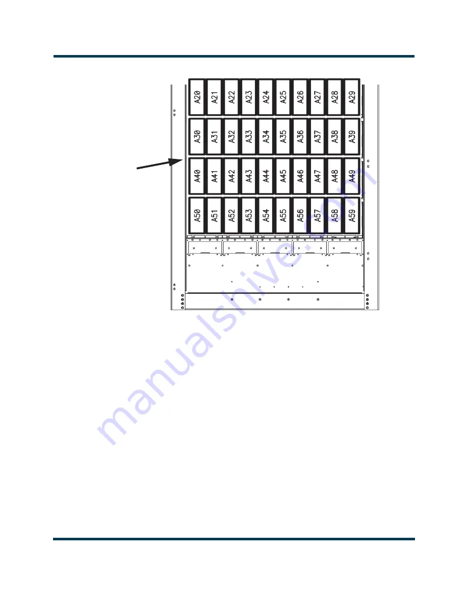
Страница 27: ...NX100 Troubleshooting Manual Responding to alarms Issue 3 2 2016 02 08 Page 1 27 LJXUH 5 3RZHU 0RGXOH RFDWLRQV 5 3RZHU 0RGXOHV URQW RRU 5HPRYHG IRU ODULW...
Страница 28: ...NX100 Troubleshooting Manual Responding to alarms Page 1 28 Issue 3 2 2016 02 08 5 3RZHU 0RGXOHV URQW RRU 5HPRYHG IRU ODULW...
Страница 29: ...MOSFET attaching hardware A soldering iron and desoldering tool An NX100 spares kit contains replacement semi conductors Electrostatic Precautions The RF power module contains semiconductor devices th...
Страница 30: ...Step 2 is not satisfactory replace the affected power amplifier MOSFET see Power Amplifier FET replacement or modulator MOSFET see Modulator FET replacement on page 1 34 4 If both measurements in Step...
Страница 31: ...to alarms Issue 3 2 2016 02 08 Page 1 31 LJXUH 5 3RZHU 0RGXOH 026 7 DQG LRGH RFDWLRQ 6RPH SDUWV UHPRYHG IRU FODULW 6 6 6 4 4 4 4 4 4 4 3DUWLDO 9LHZ RI 1 3 0RGXODWRU 3RZHU PSOLILHU 3 0RGXODWRU 026 7V...
Страница 32: ...defective MOSFET and its associated thermal pad between MOSFET and chassis 5 Ensure the surface of the chassis heat sink is clean and free of debris 6 Obtain a replacement MOSFET Nautel Part QR6868 a...
Страница 33: ...NX100 Troubleshooting Manual Responding to alarms Issue 3 2 2016 02 08 Page 1 33 LJXUH 3RZHU PSOLILHU 7 5HSODFHPHQW...
Страница 34: ...nd install it on the heat sink using the alignment post on the heat sink as an installation aid Reinstall the heat sink clip removed in Step 4 8 Replace any other defective MOSFETs and then re install...
Страница 35: ...A3 remote interface PWB A11A4 optional GPS sync PWB A11A5 and optional Exgine PWB A11A7 The control interface PWB physically interconnects with both digital AM exciter PWBs and the remote interface PW...
Страница 36: ...emote interface PWB by reversing Step 1 and Step 2 6 Reconnect all interface wiring to the new remote interface PWB Digital AM exciter PWB replacement 1 Set the transmitter to its RF Off state 2 Conne...
Страница 37: ...NX100 Troubleshooting Manual Responding to alarms Issue 3 2 2016 02 08 Page 1 37 LJXUH 1 RGH 8SORDGHU 0HQX...
Страница 38: ...ad Exciter Configuration button Select Save file to disk and click OK see Figure 1 10 on page 1 39 to save the current calibration data Browse to a desired location to save the file 7 If the defective...
Страница 39: ...l the new digital AM exciter PWB by reversing Step 8 and Step 9 11 Connect a cable between the replacement digital AM exciter PWB s RS 232 connector 9 pin D sub J3 see Figure 1 7 on page 1 36 and a PC...
Страница 40: ...New Firmware button 15 On the digital AM exciter PWB s MODE program header E1 see Figure 1 7 return the shorting jumper to the NORMAL position shorting pins 2 and 3 Press RESET switch S1 located dire...
Страница 41: ...o its RF Off state Turn off disable or lock out the ac power at the source Open the front door to gain access to the exciter panel see Figure 1 6 on page 1 35 4 Disconnect all cables attached to the c...
Страница 42: ...ttings menu See the NX100 Operations and Maintenance Manual for detailed instructions GPS Sync PWB replacement 1 Remove and retain four sets of mounting hardware from the GPS sync PWB being replaced A...
Страница 43: ...on the cables and the PWB 3 Remove and save six sets of mounting hardware 4 Remove the defective PWB from the transmitter 5 Reverse Step 1 through Step 4 to install the new PWB WARNING Lethal voltages...
Страница 44: ...oor of the cabinet There should be little or no voltage 2 Disconnect all cables attached to the RF drive distribution PWB taking note of the connector labels on the cables and the PWB 3 Carefully remo...
Страница 45: ...drive distribution PWB replacement on page 1 44 Gently pry the connectors loose with a screwdriver 3 Disconnect all cables attached to the rack interface PWB taking note of the connector labels on the...
Страница 46: ...reinstalling RF power modules on page 1 24 9 One at a time reinstall each RF power module The LED sequence on the front panel of each module should change to solid red Reconnect each RF power module...
Страница 47: ...are discharged For additional safety measure the dc voltage across the and terminals of any of the large electrolytic capacitors on the floor of the cabinet There should be little or no voltage WARNI...
Страница 48: ...fan to the SCR rectifier assembly and connect the fan s wiring as it was previously installed Return the transmitter to service 3 Disconnect all wiring attached to the SCR rectifier assembly taking n...
Страница 49: ...There should be little or no voltage 2 Disconnect all wiring attached to the affected power supply module U3 through U7 taking note of the connector labels on the cables LJXUH RFDWLRQ RI RZ 9ROWDJH 3...
Страница 50: ...ue 3 2 2016 02 08 4 Remove the power supply module from the transmitter noting its reference designation U3 through U7 should be marked on the side panel near the module 5 Reverse Step 1 through Step...
Страница 51: ...16 02 08 Page 1 51 RF Power Module Fan Tray replacement See Figure 1 16 LJXUH RFDWLRQ RI DQ 7UD VVHPEOLHV DQ 7UD VVHPEOLHV URQW RRU 5HPRYHG IRU ODULW DQ VVRFLDWHG 5 3RZHU 0RGXOH V 7UD DQ 7UD VVHPEOLHV...
Страница 52: ...ont door 2 Determine the suspect fan tray assembly A35A60 through A39A64 associated with the offending RF power module alarm s 3 Remove and save two sets of mounting hardware Pull the fan tray assembl...