


ACTIVE FILTER
Active filters are circuits with amplifiers, resistors, and capac-
itors. The use of amplifiers instead of inductors, which are
used in passive filters, enhances the circuit performance
while reducing the size and complexity of the filter.
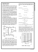
The simplest active filters are designed using an inverting op
amp configuration where at least one reactive element has
been added to the configuration. This means that the op amp
will provide "frequency-dependent" amplification, since reac-
tive elements are frequency dependent devices.
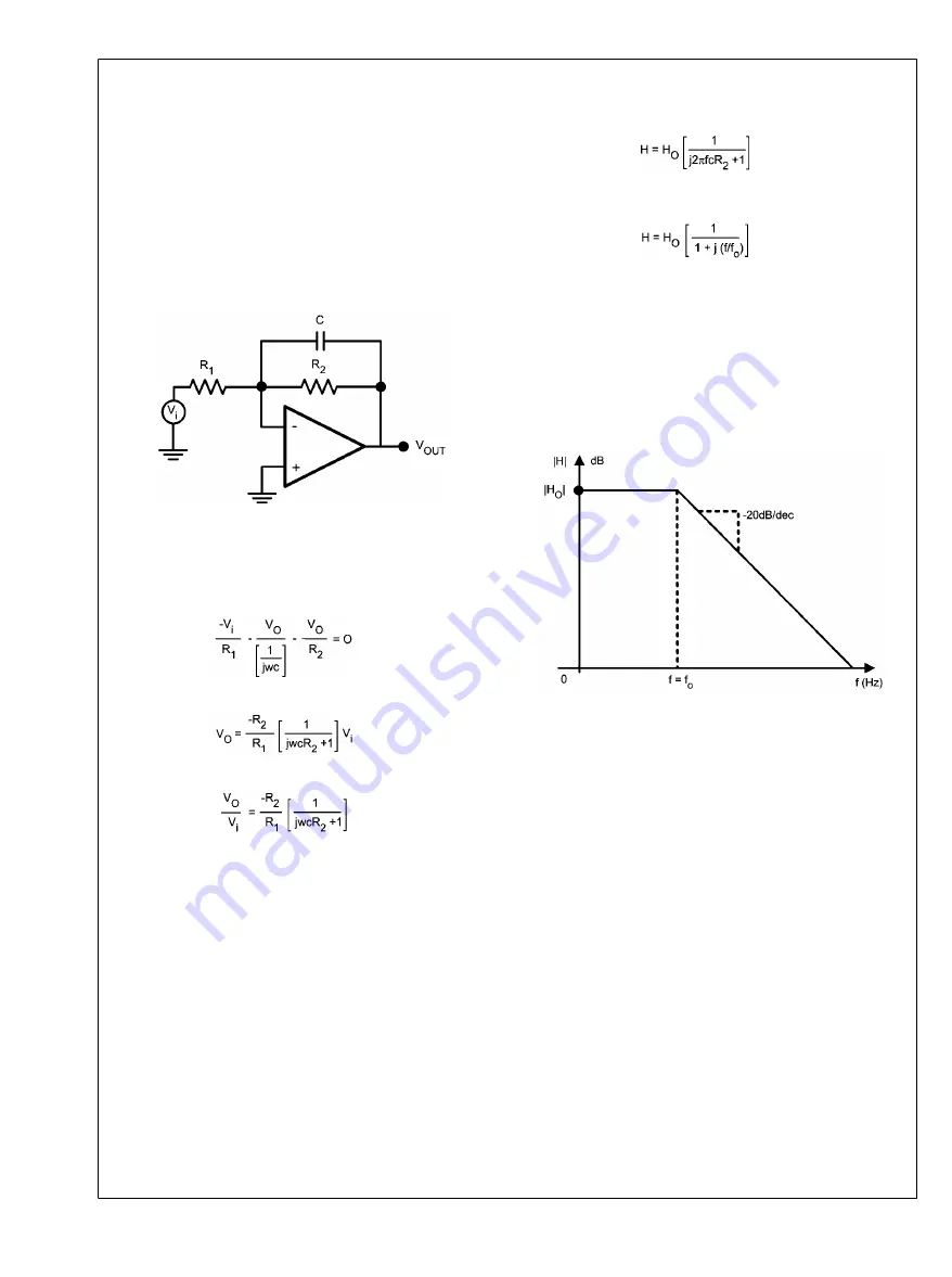
LOW PASS FILTER
The following shows a very simple low pass filter.
20039647
FIGURE 3. Lowpass Filter
The transfer function can be expressed as follows:
By KCL:
(7)
Simplifying this further results in:
(8)
or
(9)
Now, substituting
ω=2π
f, so that the calculations are in f(Hz)
and not
ω(
rad/s), and setting the DC gain H
O
= −R
2
/R
1
and
H = V
O
/V
i
(10)
Set: f
o
= 1/(2π
R
1
C)
(11)
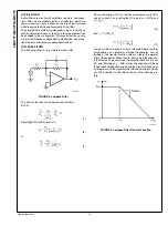
Low pass filters are known as lossy integrators because they
only behave as an integrator at higher frequencies. Just by
looking at the transfer function one can predict the general
form of the bode plot. When the f/f
O
ratio is small, the capacitor
is in effect an open circuit and the amplifier behaves at a set
DC gain. Starting at f
O
, −3dB corner, the capacitor will have
the dominant impedance and hence the circuit will behave as
an integrator and the signal will be attenuated and eventually
cut. The bode plot for this filter is shown in the following pic-
ture:
20039653
FIGURE 4. Lowpass Filter Transfer Function
www.national.com
14
LMV771/LMV772/LMV774


